Coordinated board-set manufacturing
Multi-Board PCBA Assembly for Products That Cannot Ship One Board at a Time
PCB Insider builds related PCB assemblies as controlled board sets, aligning shared BOM risk, panel strategy, AOI, X-ray, test scope, and matched-set release before one missing board delays final integration.
PCB + Harness
Cross-category support
IPC-A-610
Assembly workmanship reference
AOI + X-Ray
Inspection by package risk
BOM + ECO
Shared revision control
TL;DR
- Multi-board PCBA groups related PCB assemblies under one build plan, not separate purchase orders.
- Best fit: products with control, power, sensor, RF, and interface boards that must ship together.
- Key risk: one late component or ECO can block the entire board set release.
- We control shared BOM review, panel flow, inspection gates, and packed-set traceability.
Capability scope
Board-set assembly control starts before SMT placement
Multi-board PCBA assembly controls several related PCB assemblies as one product release. The first review looks at IPC-A-610 workmanship expectations, board revisions, shared component families, connector orientation, firmware dependency, and whether the buyer needs loose boards or matched kits.
A printed circuit board is only one part of the product when the design uses separate control, power, sensor, RF, and interface boards. Treating those PCBAs as separate jobs hides integration risk until receiving inspection, where one missing revision or connector change can stop the whole build.
PCB Insider fits best when the buyer already has released or near-released design data and wants coordinated sourcing, assembly, inspection, and pack-out. We do not take ownership of unreleased circuit design validation or safety agency certification, but we can connect multi-board PCBA to box build assembly when the next step is enclosure integration.
Capabilities built for complete product board sets
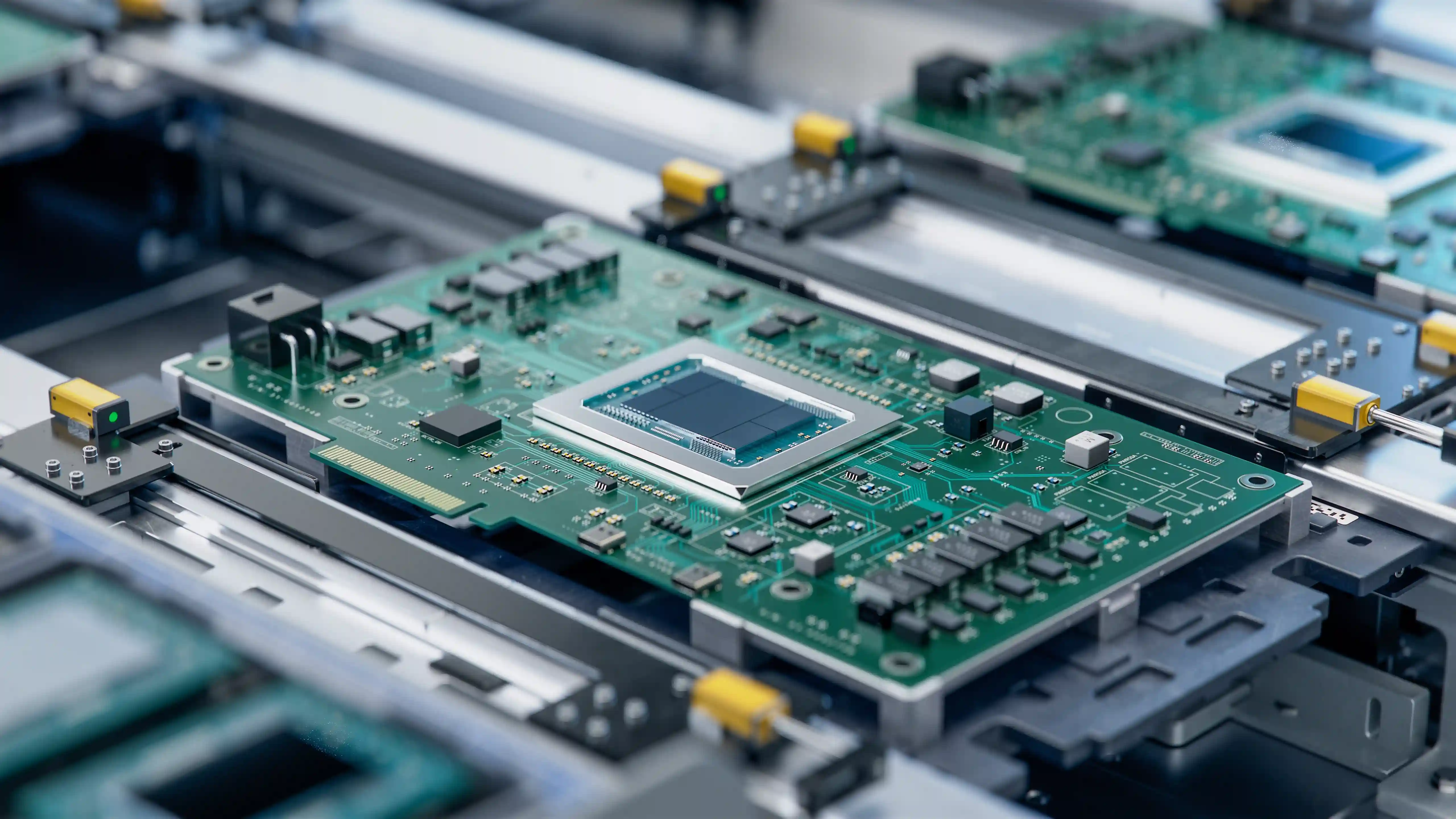
Surface-mount technology is only one production step in a board-set program. A surface-mount technology line can place the parts, but the manufacturing plan must also control panel design, through-hole sequence, solder profile, inspection coverage, and pack-out count across every related board.
Board-Set Release Planning
A multi-board PCBA is a coordinated set of printed circuit board assemblies that must function together in one product.
Panelized and Separate-Panel Strategy
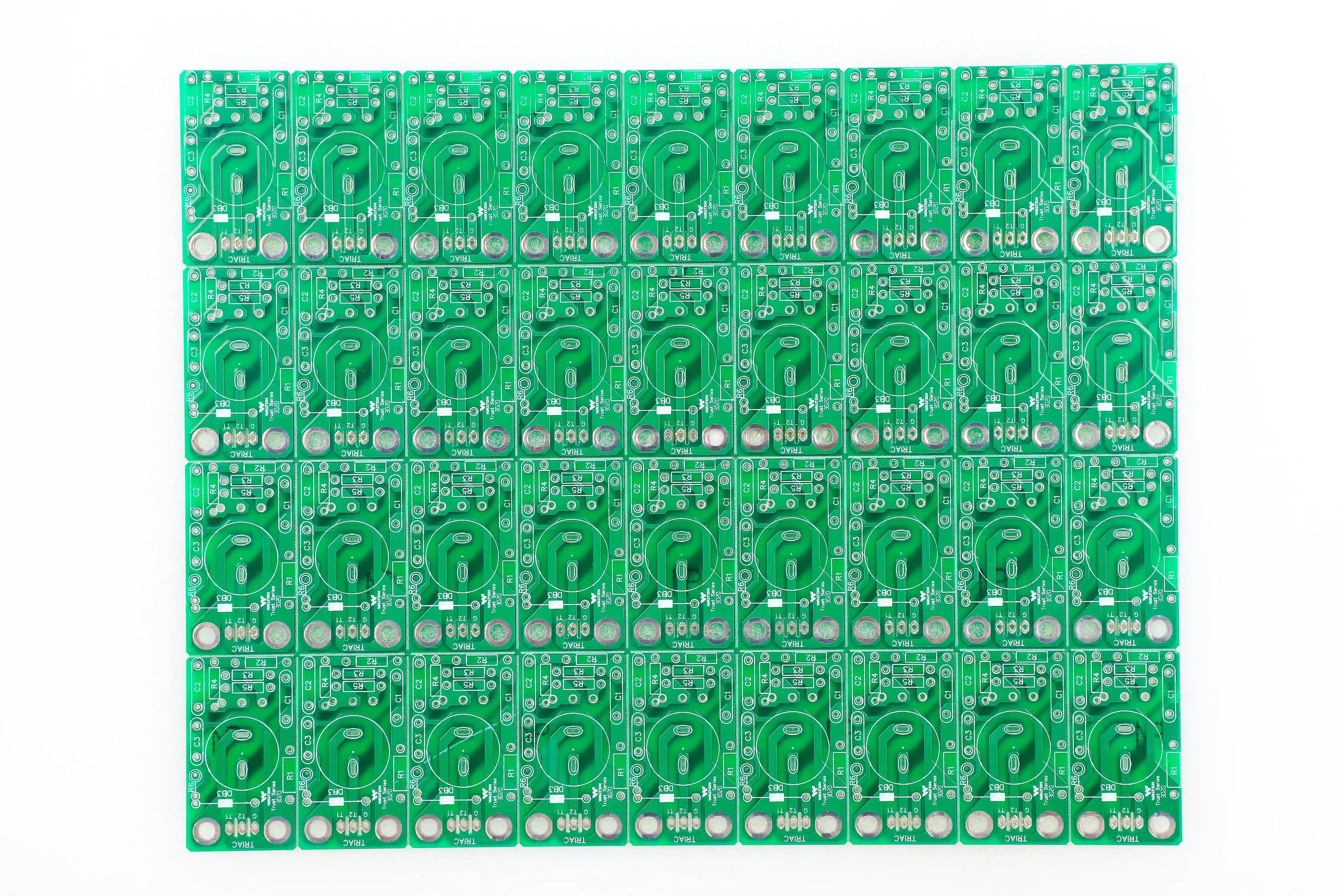
Panelized PCB assembly is a manufacturing method where multiple boards are built as an array for paste printing, SMT placement, reflow, inspection.
SMT, Through-Hole, and Mixed Board Sets
Multi-board programs often mix dense SMT logic boards with through-hole connector boards and power boards.
Shared BOM and Alternate Control
A shared BOM review catches repeated MPNs, connector pair mismatches, unavailable parts, and alternates that fit one board but not the whole product.
Inspection by Board Risk
AOI is used for visible solder and placement checks, while X-ray is assigned to BGA, QFN, LGA, and other hidden-joint packages.
Matched-Set Packing and Traceability
Finished PCBAs can be packed as matched kits by serial number, lot, hardware revision, or product configuration.
Technical scope and limits
The scope is intentionally specific: multi-board PCBA is for coordinated board sets with clear design data and a defined release objective. If the product still needs core circuit design, our electronics design services should come before the assembly quote.
| Service focus | Coordinated PCB assembly for products using 2-12 related board assemblies |
|---|---|
| Build model | Turnkey, consigned, or hybrid sourcing across the full board set |
| Assembly methods | SMT, through-hole, mixed technology, selective soldering, and wave soldering |
| Package support | 01005 passives, QFN, LGA, fine-pitch ICs, BGA, connectors, relays, and power devices |
| Data required | Gerber or ODB++, BOM, centroid, assembly drawing, board relationship notes, and test plan |
| Panel strategy | Common array or separate panels based on thickness, outline, fixture access, and component height |
| Inspection | SPI by plan, AOI, X-ray for hidden joints, ICT or functional test where defined |
| Release control | Board revision, BOM revision, ECO status, lot records, and matched-set pack-out |
| Best-fit volume | Prototype, NPI, pilot, bridge, and repeat production programs |
| Out of scope | Unreleased circuit design ownership, safety certification ownership, and undefined system validation |
Where multi-board PCBA prevents integration waste
Separate purchase orders can look cheaper until a product build waits for the one board nobody synchronized. Multi-board planning is most useful when a late ECO, connector mismatch, or missing board quantity would block system assembly.
Control + Power Board Sets
Industrial controllers, battery equipment, chargers, and motor-drive products often separate logic control from power conversion.
Display + Interface Board Sets
Medical, appliance, and industrial HMI products may include a display board, keypad board, interface board, and main controller.
RF + Digital Board Sets
Connected devices may combine an RF front-end board with a digital baseband or gateway board.
Harness-Integrated Electronics
Products with PCBAs plus cable assemblies need connector, pinout, strain-relief, and final test alignment.
Multi-board PCBA process flow
1
Map the board relationship
We identify which boards ship together, which connectors mate between boards, which firmware or test steps depend on another PCBA, and whether the customer.
2
Review data and shared BOM risk
Engineering reviews Gerber or ODB++ files, BOMs, centroid files, assembly drawings, alternates, polarity notes, and ECO status.
3
Choose panel and assembly flow
Boards are assigned to common arrays or separate panels based on outline, thickness, component height, process compatibility, and depanelization risk.
4
Inspect each board by risk class
Visible placement and solder issues are checked with AOI, while BGA, QFN, LGA, and bottom-terminated packages receive X-ray by plan.
5
Release and pack complete sets
Finished PCBAs are released with revision records, inspection status, deviation notes, and packing logic.
Choose the manufacturing model that fits the risk
IPC is the standards organization most buyers associate with electronics workmanship references, and public background on IPC electronics standards helps explain why assembly acceptance criteria matter. The purchasing decision still depends on product structure: one board, several related boards, or full box build.
| Model | What it controls | Best use |
|---|---|---|
| Separate PCBA orders | Each board quoted and built independently | Simple products where boards do not affect each other |
| Multi-board PCBA | Related boards controlled under one sourcing, assembly, and release plan | Products where missing one board blocks final integration |
| Single panel array | Multiple board designs placed on one manufacturing panel | Similar thickness, finish, assembly side, and depanelization requirements |
| Separate panels | Each board has its own optimized array and assembly route | Different thickness, high components, special test access, or RF laminate needs |
| Box build assembly | PCBAs are installed with wiring, enclosure hardware, labels, and system test | Buyer wants installation-ready subassemblies instead of loose PCBAs |
The practical rule is simple: use separate orders only when the boards are operationally independent. Use multi-board PCBA when a missing or mismatched board blocks final assembly. Move to box build when PCBAs, cable assemblies, enclosure hardware, labels, firmware, and system test need one controlled release.
Expert note from Hommer Zhao
"The mistake I see in multi-board programs is quoting each board like it lives alone. If one connector, one STM32-family controller, or one firmware-loaded board changes late, the whole product waits. The RFQ should show the board relationship, not just the Gerbers."
Evidence grade
Verified project evidence supports ISO 9001:2015 positioning, PCB assembly, wire harness, and EMS scope across the site.
Board-set quantity ranges and process choices are capability boundaries for RFQ planning, not fixed guarantees for every design. Final scope is confirmed after file review.
Multi-board PCBA FAQ
What is multi-board PCBA assembly?
Multi-board PCBA assembly is coordinated PCB assembly for a product that uses 2 or more related circuit boards. Instead of treating each board as a separate job, the build controls shared BOM items, board revisions, inspection gates, test dependencies, and matched-set packing together. This approach is useful when a controller board, power board, RF board, or interface board must arrive as a complete kit for final integration.
I have 4 different PCBAs for one product. Should they be built together or separately?
Four related PCBAs should usually be quoted and planned together, even if they run on separate SMT panels. Joint planning exposes shared components, connector mating risks, ECO timing, and test dependencies before production starts. The boards may still use different process routes if one has BGA devices, another uses through-hole connectors, and another needs RF material control. The release plan should keep the product set synchronized.
Can different board designs share one PCB assembly panel?
Different board designs can share one panel when thickness, copper weight, surface finish, assembly side, component height, breakaway-tab placement, and depanelization clearance are compatible. A shared panel can reduce handling and setup time, but it is not always the right choice. If one board has tall connectors or fragile edge features, separate panels may protect yield better than forcing every board into one array.
What files do you need for a multi-board PCBA quote?
A multi-board PCBA quote needs Gerber or ODB++ files, BOMs, centroid files, assembly drawings, quantity per board, revision status, and notes explaining how the boards relate to each other. If the boards connect through cables, headers, board-to-board connectors, or enclosure hardware, include mating connector part numbers and pinout notes. Test requirements should identify whether each board needs AOI, X-ray, ICT, functional test, or kit-level verification.
How do you prevent one missing part from delaying the whole board set?
We screen the full board-set BOM before release and flag components that appear on multiple boards, have long lead times, or need approved alternates. A single unavailable IC, connector, or regulator can block 3 or 4 PCBAs at once. For turnkey builds, we separate critical-path parts from commodity passives and ask for alternate approval early enough to protect the complete matched-set delivery date.
My project includes PCBAs and wire harnesses. Can you coordinate both?
Yes. PCB Insider supports PCB assembly, wire harness manufacturing, cable assembly, and box build assembly, so cross-category programs can be handled under one release plan. A common pattern is a buyer adding PCB/PCBA work to an existing harness relationship, which expands across categories and engages multiple departments. The key is to define connector interfaces, pinouts, test scope, and pack-out logic before production.
When should I choose box build assembly instead of multi-board PCBA only?
Choose multi-board PCBA when you need assembled boards delivered as loose or matched PCB sets. Choose box build assembly when those boards also need enclosure installation, internal wiring, labeling, firmware loading, system-level test, and final packaging. The decision changes the quote package because box build needs mechanical drawings, harness drawings, torque or fastening notes, labels, and acceptance criteria in addition to the PCBA files.
Related manufacturing services
Multi-board PCBA usually sits between individual PCB assembly and full box build. These service pages define the adjacent scope so the RFQ can land in the right workflow.
PCB Assembly
SMT, through-hole, BGA, and turnkey PCB assembly for individual board builds.
SMT Assembly
Surface mount assembly for fine-pitch packages, prototypes, NPI, and production.
PCBA Quality Assurance
FAI, inspection records, PFMEA inputs, 8D support, and release documentation.
Box Build Assembly
PCBA, wiring, enclosure, labeling, system test, and final pack-out integration.
Get a quote for a complete multi-board PCBA set
Send the Gerber or ODB++ files, BOM, centroid data, assembly drawings, quantity per board, and notes showing how the boards connect. We will review the set as one manufacturing release instead of isolated PCBAs.
Start the board-set RFQ