Fixtureless Electrical Test for NPI PCBAs
Flying Probe Testing Service Before ICT Fixture Spend
PCB Insider uses flying probe testing for prototype, NPI, and low-volume PCB assemblies where buyers need electrical fault coverage before a dedicated ICT fixture is justified. The differentiator is practical coverage mapping: flying probe, X-ray, ICT, and functional test each get a clear job before the lot is released.
0 fixture
No bed-of-nails tooling required
NPI
Prototype and bridge-build fit
IPC-A-610
Assembly acceptability context
24 hours
Quote review for complete files
TL;DR
- Flying probe testing screens prototype and low-volume PCB assemblies without a dedicated ICT fixture.
- It is strongest for opens, shorts, passive checks, polarity checks, and early NPI fault isolation.
- It is slower than ICT per board, but avoids fixture cost when designs are changing.
- PCB Insider maps flying probe, ICT, X-ray, and functional test before production release.
Fixtureless Test Is the Practical NPI Gate
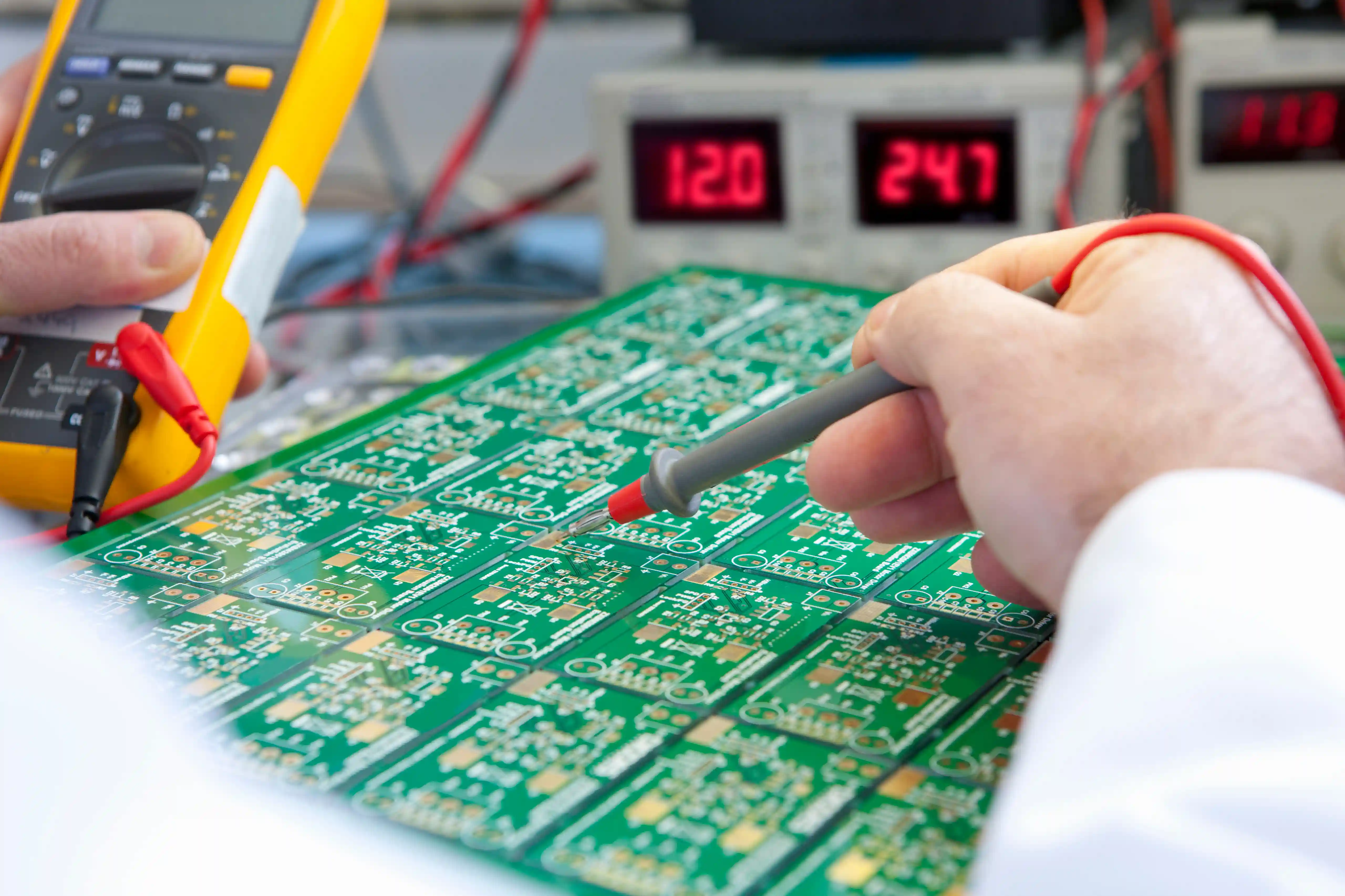
Flying probe testing is a fixtureless in-circuit electrical test method that contacts PCB assembly nodes with moving probes instead of a fixed pin bed. A flying probe test is a PCBA screening method for low-volume builds that need electrical evidence without custom tooling. A bed-of-nails ICT fixture is a dedicated production tool that contacts many test points at once. Design for test is the PCB layout practice that makes either method more effective.
Public references on flying probe, in-circuit testing, and IPC electronics standards explain why access, workmanship, and fault coverage must be separated. IPC-A-610 can frame finished assembly acceptability, but it does not decide whether a 75-board prototype lot deserves a custom ICT fixture. That decision depends on revision stability, board access, net count, failure risk, and the buyer's release evidence requirement.
Fixtureless Electrical Screening
Flying probe testing uses programmable moving probes to contact pads, vias, component pins, and test points. That lets engineering screen a new PCBA revision before paying for a fixed bed-of-nails fixture.
Open and Short Detection
Net-level checks identify open traces, solder bridges, power-to-ground shorts, and isolation problems that visual inspection cannot prove. This is useful after SMT reflow, selective soldering, or rework.
Component Value and Polarity Checks
The test plan can verify selected resistors, capacitors, diodes, LEDs, connector pins, and polarity-sensitive parts where circuit access allows stable measurement without damaging the assembly.
ICT Decision Support
Flying probe data helps buyers decide whether a recurring build justifies ICT fixture investment. When annual volume is still uncertain, fixtureless test keeps NPI moving while the design stabilizes.
DFT Feedback for the Next Revision
Test access issues are documented as practical design-for-test feedback: blocked pads, inaccessible nets, missing ground reference points, dense BGA escape areas, and fixture-risk locations.
Buyer-Readable Test Evidence
Release packages can include board revision, test method, pass/fail result, fault location notes, rework disposition, and lot-level traceability when the purchase order requires evidence.
Capability Scope and Limits
Flying probe testing fits designs where electrical fault coverage is valuable but fixture lock-in is premature. It does not replace AOI, X-ray, ICT, or functional test; it sits between visual inspection and powered validation when the release plan needs fixtureless fault isolation.
| Service focus | Fixtureless flying probe testing for assembled PCB and selected bare-board or NPI verification needs |
|---|---|
| Best-fit stage | Prototype, EVT, DVT, pilot, low-volume production, ECO validation, and bridge builds before ICT fixture release |
| Typical fault coverage | Opens, shorts, resistance checks, selected capacitance checks, diode polarity, LED polarity, connector continuity, and net isolation |
| Input files | Gerber or ODB++, NC drill, netlist, BOM, centroid, schematic when available, assembly drawing, IPC class, and test priorities |
| Companion checks | AOI, X-ray for hidden joints, ICT for recurring production, programming, and final functional test |
| Quality references | IPC-A-610 workmanship context, IPC-J-STD-001 soldering expectations, ISO 9001:2015 document control discipline |
| Lead-time signal | 24-hour engineering quote review for complete data; test programming time depends on access, net count, and fault coverage target |
| Out of scope | RF conformance, safety certification, unreleased firmware debugging, and full functional validation without buyer-approved limits |
Engineering Note
"A flying probe pass should not be treated as proof that the product works. It proves specific accessible electrical conditions. For NPI, that is often exactly what the buyer needs: catch assembly faults, learn which nets are hard to access, and delay ICT fixture spend until the PCB revision stops moving."
Hommer Zhao, Founder & Technical Expert
Flying Probe vs ICT vs Functional Test
The correct test method depends on the buyer's decision point. Flying probe protects prototype and low-volume PCBAs from obvious electrical escapes. ICT improves production speed after a fixture is justified. Functional testing proves powered behavior only after the buyer defines exact limits.
| Buyer situation | Best starting point | Reason |
|---|---|---|
| Early prototype with weekly ECOs | Flying probe | Avoids fixture spend while pads, nets, and components are still changing. |
| Low-volume pilot below fixture payback | Flying probe | Gives electrical fault coverage without locking the buyer into a custom fixture. |
| Stable high-volume PCBA | ICT | Dedicated fixture cost is easier to justify when throughput and repeatability matter more than flexibility. |
| Dense BGA with poor test access | X-ray + boundary scan review | Flying probe cannot physically reach every hidden joint or JTAG-accessible digital fault. |
| Shipment acceptance depends on powered behavior | Functional test | Flying probe finds assembly faults; functional test proves the product response under power. |
Flying Probe Test Workflow
The workflow is designed to prevent two common NPI mistakes: treating fixtureless test as complete functional validation, and releasing an ICT fixture before test access is stable.
1
Review access and data completeness
Engineering reviews Gerber or ODB++, BOM, centroid, netlist, schematic, and assembly notes to identify accessible nets, no-test zones, and coverage limits.
2
Define the fault model
The buyer and test engineer agree which faults matter most: shorts, opens, passive values, connector continuity, diode polarity, first-article screening, or ECO comparison.
3
Program fixtureless probe paths
Probe locations, measurement limits, guard points, board orientation, and safe contact rules are programmed before the first article is tested.
4
Test first articles and classify failures
Initial boards are screened, suspected faults are reviewed against AOI or X-ray evidence, and false failures are separated from real assembly defects.
5
Release evidence and DFT feedback
Pass/fail results, fault notes, rework disposition, and design-for-test recommendations feed into the next PCB revision or the ICT fixture decision.
FAQs for Buyers
These answers are written for RFQ-stage engineers deciding how to test a new or low-volume PCBA build.
What is flying probe testing for PCB assembly?
Flying probe testing is a fixtureless electrical test for PCB assemblies that uses programmable moving probes instead of a custom bed-of-nails fixture. It checks accessible nets for opens, shorts, selected component values, connector continuity, and polarity-sensitive parts. It is a strong fit for prototype, EVT, DVT, and low-volume PCBA builds because the test program can change with the board revision before the buyer commits to ICT fixture cost.
I need 50 prototype PCBAs next month. Is flying probe better than ICT?
Flying probe is usually better than ICT for 50 prototype PCBAs when the design may still change and fixture payback is weak. ICT can test faster per board, but a custom fixture adds cost, schedule, and revision risk. For a 50-piece NPI lot, PCB Insider normally starts with AOI, X-ray where hidden joints matter, flying probe for accessible electrical faults, and a functional test only where powered behavior controls shipment acceptance.
What files do you need for a flying probe testing quote?
A useful flying probe testing quote needs Gerber or ODB++, NC drill, netlist, BOM, centroid, assembly drawing, schematic if available, board revision, quantity, IPC class, and the faults you want prioritized. If the board has dense BGA or fine-pitch areas, include X-ray requirements and design-for-test notes. Missing netlist or schematic data can limit coverage because probe programming depends on knowing which nodes should connect and which must remain isolated.
Can flying probe testing replace functional testing?
Flying probe testing cannot replace functional testing when the buyer needs proof of powered product behavior. Flying probe is strongest for assembly-level electrical faults such as opens, shorts, wrong values, and selected polarity issues. Functional test checks boot, current draw, communications, sensors, relays, displays, or firmware response under power. Many PCBA release plans use both: flying probe to isolate assembly defects, then functional test to confirm the board performs its required job.
When should I move from flying probe to ICT?
Move from flying probe to ICT when the PCB revision is stable, the build repeats, and test throughput matters more than fixture flexibility. A dedicated ICT fixture can reduce cycle time and improve repeatability for recurring production, but it becomes risky when pads, components, or enclosure constraints are still changing. PCB Insider uses flying probe results and DFT feedback to identify which test points and fixture contacts should be locked before ICT hardware is released.
What standards matter for flying probe PCBA testing?
IPC-A-610 and IPC-J-STD-001 matter because flying probe results sit inside a larger assembly acceptance process, not outside it. ISO 9001:2015 discipline matters for document control, traceability, and released test records. The test method itself must still be defined by the buyer's fault model: which nets are critical, which values need measurement, what revision is active, and whether pass/fail evidence must ship with each lot.
What are the limits of flying probe testing?
Flying probe testing is limited by physical access, measurement stability, board geometry, component behavior in-circuit, and cycle time. It cannot inspect hidden BGA joints like X-ray, cannot prove complete product behavior like functional test, and may be too slow for high-volume production. Its advantage is flexibility: for prototype and low-volume PCB assemblies, fixtureless programming gives useful electrical coverage before the design and production plan are fully locked.
Related Services
ICT Testing Service
Use fixture-based in-circuit testing when recurring production needs faster cycle time and repeatable net-level fault isolation.
Test Fixture PCB
Build pogo-pin adapters, bed-of-nails boards, and functional test fixture electronics after the design stabilizes.
PCBA Programming & Functional Testing
Add firmware loading and powered pass/fail checks when shipment acceptance depends on product behavior.
PCBA Quality Assurance
Connect flying probe results to first article review, release records, and corrective action evidence.
Technical Reading
Flying Probe vs ICT for PCB Assembly
Compare fixtureless and fixture-based electrical test by cost, coverage, throughput, and DFT requirements.
Test Fixture Readiness for PCB Assembly
Use this guide when a low-volume flying probe plan is ready to move toward recurring fixture-based screening.
Boundary Scan Testing in PCB Assembly
See how JTAG coverage fits when dense packages reduce physical probe access.
Get a Flying Probe Test Plan Before Fixture Spend
Send Gerber or ODB++, netlist, BOM, centroid, schematic if available, assembly drawing, target quantity, and the faults you need covered. PCB Insider will review whether flying probe, ICT, X-ray, functional test, or a hybrid plan fits the build.
Request Flying Probe Testing Quote