Aluminium PCB Manufacturer
Metal core PCB fabrication with thermal conductivity up to 8.0 W/mK, dielectric breakdown voltage to 12 kV, and copper weights from 1oz to 4oz. We deliver single-layer MCPCBs in 3 working days for prototypes, and hold thermal resistance variation under 8% across production lots — a number most suppliers will not even measure, let alone guarantee.

Why Aluminium PCBs Exist — And When You Actually Need One
Standard FR-4 has a thermal conductivity of roughly 0.3 W/mK. That number is fine for low-power digital boards where the total dissipation is under 2W. But the moment you put a high-power LED, a MOSFET, or a motor driver IC on that same substrate, heat has nowhere to go. The junction temperature climbs, the component degrades faster, and your MTBF drops off a cliff. Aluminium PCBs solve this by replacing the FR-4 core with a metal base that conducts heat 500-700x better.
But here is the catch — and this is the part most guides do not mention: the aluminium itself is not the thermal bottleneck. The dielectric layer between your copper circuit and the aluminium base is. That thin polymer film (typically 75-100µm) has a thermal conductivity of 1.0-8.0 W/mK depending on the material grade. So the real engineering decision is not "should I use aluminium?" but "what dielectric do I specify, and how thick?" Get that wrong and you have an expensive aluminium board that performs only marginally better than FR-4.
We manufacture aluminium PCBs across a wide range of MCPCB designs — LED boards, motor controllers, power supplies, automotive lighting, and thermal management boards. Our production line is dedicated to metal core construction, not a side operation running FR-4 boards between MCPCB lots. That specialization matters because lamination parameters, etching chemistry, and routing tooling are all different for aluminium substrates.
According to IPC-4101, the material specification standard for rigid base materials, metal core substrates fall into specific slash sheets that define dielectric properties, copper foil adhesion, and thermal cycling performance. We build to those standards and can provide material certifications on request. Reference: IPC Standards (Wikipedia).
Aluminium PCB Capabilities
High Thermal Conductivity Dielectrics
We stock dielectric materials from 1.0 W/mK up to 8.0 W/mK. Standard FR-4 has roughly 0.3 W/mK — our entry-level MCPCB dielectric already triples that.
1-4 Layer MCPCB Constructions
Single-layer aluminium PCB is the most common — copper circuit layer, dielectric, aluminium base.
Power Electronics Optimized
Aluminium PCBs for power applications face different demands than LED boards.
Automotive and UL Certified
Our aluminium PCB production line runs under IATF 16949 for automotive and ISO 9001:2015 for general industry.
Precision Etching and Routing
Copper etching on MCPCBs requires tighter process control than standard FR-4 because the copper is often heavier (2-4oz) and the dielectric does not tolerate.
Surface Finishes for LED and Soldering
ENIG (Electroless Nickel Immersion Gold) is our default finish for MCPCBs — it provides a flat surface for LED placement and wire bonding, and the gold.
MCPCB Specification Comparison
The table below shows what we build versus what the industry typically offers. Pay attention to the dielectric thermal conductivity and breakdown voltage rows — those two parameters determine whether your board actually solves a thermal problem or just adds cost.
| Parameter | Industry Standard | Our Capability | Notes |
|---|---|---|---|
| Dielectric Thermal Conductivity | 1.0 W/mK | 1.0 - 8.0 W/mK | 8.0 W/mK uses ceramic-filled polymer |
| Dielectric Breakdown Voltage | 4 kV | 4 - 12 kV | High-voltage grade for power electronics |
| Aluminium Base Thickness | 0.8 - 1.5mm | 0.8 - 3.0mm | 5052 and 6061 alloys available |
| Copper Weight | 1 - 2 oz | 1 - 4 oz | 4oz for high-current power traces |
| Layer Count | 1 layer | 1 - 4 layers | Multi-layer with thermal via arrays |
| Min Trace/Space (1oz) | 6/6 mil | 4/4 mil | 8/8 mil on 3oz copper |
| Thermal Resistance Variation | Not measured | <8% lot-to-lot | Verified by hot disk analyser per lot |
| Prototype Lead Time | 7-10 days | 3-5 days | Single-layer, standard materials |
Thermal conductivity values measured per ASTM D5470. Breakdown voltage tested per IEC 60243-1. All specifications subject to DFM review — some combinations (e.g., 4oz copper with 4/4 mil traces) are not achievable regardless of supplier claims.
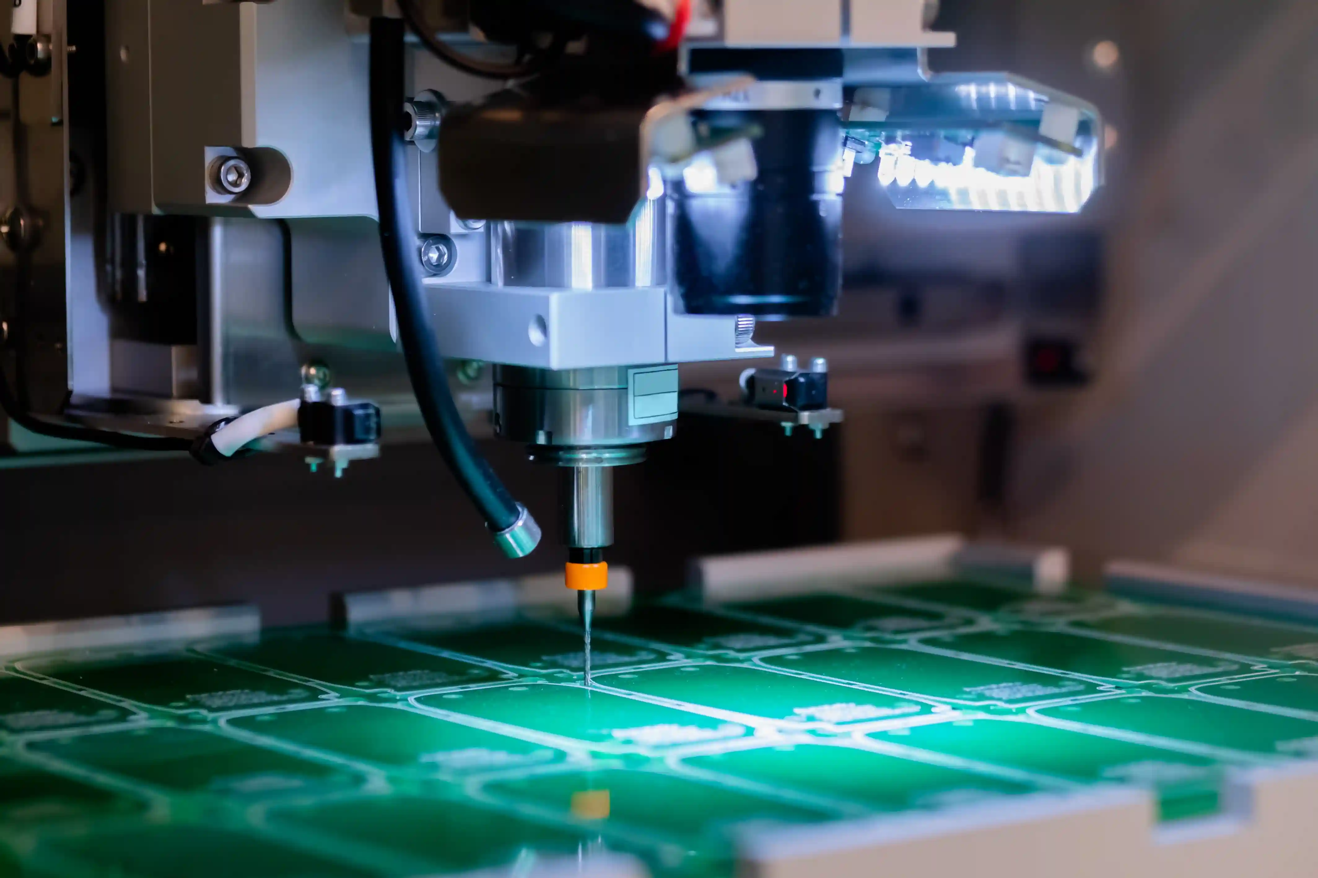
Aluminium PCB Manufacturing Process
MCPCB fabrication shares some steps with FR-4 production but diverges significantly at lamination, etching, and routing. Understanding these differences helps you design for manufacturability — and avoid the costly DFM re-spins we see every week.
1
DFM Review and Thermal Consultation
Every aluminium PCB order starts with a DFM check that goes beyond standard copper checks.
2
Material Selection and Lamination
We stock aluminium 5052 (0.8mm, 1.0mm, 1.5mm, 2.0mm, 3.0mm) and 6061 for thicker structural boards.
3
Circuit Patterning and Etching
Photoimageable dry film is applied to the copper layer, exposed through your Gerber artwork, and developed.
4
Solder Mask, Legend, and Surface Finish
Solder mask on MCPCBs serves double duty — it prevents solder bridging and also defines the thermal interface area.
5
CNC Routing, V-Scoring, and Inspection
Board outline is CNC routed with carbide bits designed for aluminium — standard FR-4 routing bits dull within 10 panels on MCPCB material.
6
Packaging and Shipment
Aluminium PCBs are heavier and more rigid than FR-4, which means they are less prone to flex damage but more prone to surface scratching.
Choosing the Right Dielectric: A Decision Framework
This is the decision that matters most on an aluminium PCB project, and most online guides gloss over it with a simple "pick higher thermal conductivity." That advice is wrong — or at least incomplete. Higher thermal conductivity dielectrics cost more, sometimes 3-5x the price of standard 1.0 W/mK material. And if your application does not need it, you are burning budget for zero benefit.
Here is our decision framework, built from actual thermal simulations and post-production testing on thousands of boards:
| Application Power Density | Recommended Dielectric | Typical Cost Premium | When to Use |
|---|---|---|---|
| < 5 W/cm² | 1.0 W/mK (standard) | Baseline | Indicator LEDs, low-power drivers |
| 5 - 15 W/cm² | 1.5 - 2.0 W/mK | +15-25% | LED arrays 10-30W, small motor drives |
| 15 - 30 W/cm² | 3.0 - 4.5 W/mK | +40-80% | High-power COB LEDs, power supplies |
| > 30 W/cm² | 5.0 - 8.0 W/mK | +100-200% | IGBT modules, extreme LED, RF power amps |
Power density calculated as total dissipation divided by dielectric contact area under the thermal pad. If your thermal pad is 5mm × 5mm and the component dissipates 5W, that is 20 W/cm² — you need 3.0+ W/mK dielectric. These thresholds are based on keeping junction temperature rise under 40°C above ambient with natural convection on the aluminium base. Forced air cooling shifts these thresholds upward. Reference: JEDEC thermal measurement standards (jedec.org).
Quality Control That Actually Measures Thermal Performance
Most PCB suppliers test aluminium boards the same way they test FR-4: electrical continuity, impedance, visual inspection. That covers electrical function but completely ignores the primary reason you chose aluminium — thermal management. We consider that a gap you cannot afford.
Every production lot gets a thermal resistance spot-check using a Hot Disk TPS 2500S analyser. We measure Rth from the copper surface through the dielectric to the aluminium base, and we log that data against the material certificate. If thermal resistance exceeds the specified value by more than 8%, the lot is quarantined and re-tested. In 2025, our quarantine rate was 0.3% — three lots out of a thousand. All three were traced to a lamination pressure drop caused by a worn hydraulic seal.
We also perform thermal cycling per IPC-TM-650 2.6.7 on sample boards from each new part number: 100 cycles from -40°C to +125°C, then re-measure thermal resistance and dielectric adhesion. If adhesion drops below 1.0 N/mm (peel strength per IPC-TM-650 2.4.8), we adjust the lamination recipe before production. This is the kind of validation that separates a board that survives field conditions from one that delaminates after two winters.
Representative Application: Automotive LED Headlight Module
Challenge
A typical automotive LED headlight program needs MCPCBs for an LED headlight assembly. A representative design uses about a dozen high-power LEDs per board, each dissipating several watts, on a compact board. A low-conductivity (1.0 W/mK) dielectric can let junction temperatures hit 145°C in thermal chamber testing at 85°C ambient — above the 125°C maximum a typical LED datasheet allows — driving elevated field failures.
Solution
We redesigned the thermal stackup: 2.0 W/mK dielectric at 75µm thickness (down from 100µm), 1.5mm 5052 aluminium base, and 2oz copper with expanded thermal pads under each LED. Added thermal vias (0.3mm filled) connecting the thermal pads directly to the aluminium base through the dielectric. White LPISM solder mask for maximum reflectivity. Surface finish: ENIG 3µin Au / 150µin Ni. Full PPAP documentation per AIAG Level 3.
Results
A higher-conductivity stackup like this can drop junction temperature to roughly 118°C at 85°C ambient — safely within the 125°C limit — and roughly halve thermal resistance per LED pad. Field failures fall sharply; the modest board-cost increase is typically offset by a large reduction in warranty cost. Typical lead time is about 4 weeks for first article and 3 weeks ongoing, with IATF 16949 process discipline throughout.
Common Aluminium PCB Design Mistakes We Catch in DFM
Specifying aluminium without specifying the dielectric
We see this weekly. The BOM says "aluminium PCB" and nothing else. The dielectric is 70% of the thermal resistance in the stackup. If you do not specify it, you get whatever the supplier has in stock — usually 1.0 W/mK. That may or may not work for your application. Always specify dielectric thermal conductivity, thickness, and breakdown voltage.
Thermal pads smaller than the component footprint
On FR-4, a small thermal pad is a minor inconvenience. On MCPCB, the copper-to-dielectric-to-aluminium path is your primary heat exit. If the thermal pad is 3mm × 3mm under a 5mm × 5mm LED, you are leaving 64% of your thermal conductance on the table. Make the thermal pad as large as the component allows — and connect it to the aluminium through the dielectric with no solder mask interruption.
Ignoring thermal contact resistance to the heatsink
The aluminium base conducts heat beautifully — but only if it actually contacts the heatsink. We have seen designs where the aluminium base had a natural oxide layer and no thermal interface material specified. That oxide adds 0.5-1.0°C/W of contact resistance. Specify thermal grease or a gap pad, and ensure the mounting screws apply even pressure. (Ask me how I know — we had a customer return boards as "defective" because they bolted the aluminium base directly to an anodized heatsink with no paste. Two surfaces of oxide. Thermal resistance was astronomical.)
V-scoring aluminium without specifying deburring
V-scoring aluminium leaves sharp edges and burrs on the score line. If your assembly workers handle these boards bare-handed, they will get cut. If the board slides into a connector, the burrs can short exposed contacts. We always flag this in DFM and offer mechanical deburring or individual routing as alternatives. Routing costs more but eliminates the safety and reliability risk entirely.
Related Services
PCB Manufacturing
Full-range PCB fabrication from FR-4 standard to high-frequency and high-TG materials for all applications.
Learn MorePCB Assembly (PCBA)
SMT and through-hole assembly including reflow soldering on MCPCB substrates with modified thermal profiles.
Learn MoreRigid-Flex PCB Fabrication
Combined rigid and flexible circuit constructions for space-constrained and dynamic bend applications.
Learn MoreAutomotive PCB Manufacturing
IATF 16949-aligned PCB manufacturing for EV, lighting, power, and control electronics that need launch evidence.
Learn MoreFrequently Asked Questions
What is the minimum order quantity for aluminium PCBs?
Our MOQ for aluminium PCBs starts at 5 pieces for prototypes and 100 pieces for production runs. Single-layer MCPCBs can be delivered in 3-5 working days for urgent prototypes. For multi-layer aluminium boards (2-4 layers), prototype MOQ is 10 pieces with a 7-10 day lead time.
How much thermal conductivity do I need for my LED application?
For most single LED applications under 3W, standard 1.0 W/mK dielectric is sufficient. High-power LED arrays (10W+) typically require 1.5-2.0 W/mK. For extreme power density above 50W on a single board, we recommend 3.0-8.0 W/mK dielectric materials like Bergquist HT-04503 or similar. The junction-to-case thermal resistance of your LED package also factors in — check the manufacturer datasheet for Rth(j-c) values.
Can you assemble components on aluminium PCBs?
Yes. We offer full SMT assembly on aluminium PCBs including reflow soldering with modified profiles to account for the aluminium substrate's higher thermal mass. Typical reflow peak temperature for MCPCBs is 245-255°C with extended soak times. We handle LED placement, driver ICs, and through-hole power components. IPC-A-610 Class 2 and Class 3 inspection standards apply.
What is the difference between aluminium PCB and copper core PCB?
Aluminium core PCBs use an aluminium alloy base (typically 5052 or 6061) and cost 30-50% less than copper core equivalents. Copper core PCBs offer roughly 2x better thermal conductivity (up to 400 W/mK vs 205 W/mK for the metal layer) but at significantly higher material cost. For most LED and power applications, aluminium provides sufficient thermal management. Copper core is reserved for extreme cases like IGBT modules or high-current bus bars where thermal resistance must be minimized below 0.1°C/W.
What file formats do you accept for aluminium PCB quotes?
We accept Gerber files (RS-274X), ODB++, and IPC-2581 format. For aluminium PCBs specifically, please include a mechanical layer defining the aluminium thickness, a dielectric layer with thermal conductivity specification, and any routing or V-score requirements. DXF files are helpful for non-standard outline shapes. Our CAM team reviews every file within 4 hours and flags any DFM issues related to the metal core construction.
What certifications do your aluminium PCBs carry?
Our aluminium PCBs are manufactured under ISO 9001:2015 and IATF 16949 quality systems. We offer UL 94V-0 rated dielectric materials and can provide UL file numbers upon request. Automotive-grade boards comply with AEC-Q200 requirements. RoHS and REACH compliance is standard on all production. IPC Class 3 inspection is available for critical applications with 100% electrical testing.
How does the dielectric layer thickness affect thermal performance?
The dielectric layer is the primary thermal bottleneck in an MCPCB stackup. A standard 100µm dielectric at 1.0 W/mK has a thermal resistance of approximately 0.1°C·cm²/W. Reducing it to 75µm cuts thermal resistance by 25%, and using a 2.0 W/mK material at 75µm drops it to roughly 0.038°C·cm²/W — a 62% improvement. However, thinner dielectric reduces dielectric breakdown voltage, so there is a trade-off. For boards operating above 500V, we recommend maintaining at least 100µm dielectric thickness with high-breakdown-strength materials.
Ready to Specify Your Aluminium PCB?
Send us your Gerber files, stackup requirements, and thermal targets. Our CAM engineers review every MCPCB design within 4 hours and provide a detailed DFM report with thermal resistance estimates before you commit to production. No charge for the review — we would rather catch problems upfront than build boards that fail in the field.
Reviewed by: Engineering Team, PCB Insider | Last updated: 2026-04-17 | References: IPC-4101, IPC-6012, IPC-TM-650, ASTM D5470, IEC 60243-1, UL 94