PCB Assembly Process: All You Need To Know
The PCB assembly process comes right after the PCB manufacturing process to weld the components on the solder pads.
The PCB assembly process comes right after the PCB manufacturing process to weld the components on the solder pads.
So all circuit boards must undergo professional assembly to become functional in their respective application areas.
Essentially, they transition from PCBs to PCBAs after component welding, and we’ll look at this assembly process in detail below. Read on to learn more!
PCB Assembly Technologies
The PCB assembly process varies slightly depending on the assembly technology. So let’s look at these technologies first.
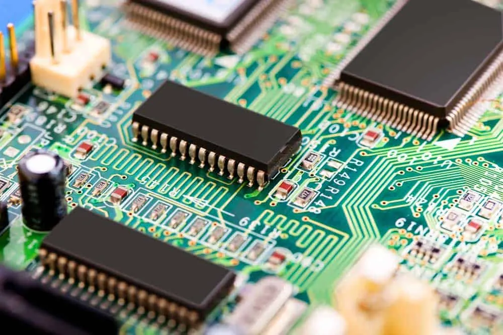
Surface-Mount Technology (SMT)
SMT involves assembling surface-mount devices on the circuit board. These devices are usually tiny and sit on component pads instead of going through, hence the name.
SMT electronic components take up little real estate, but you must control the solder paste application and part placement.
This precise application will ensure accurate welding and sturdy solder joints.
So the SMT assembly process must take these factors into account. And it occurs using the following steps.
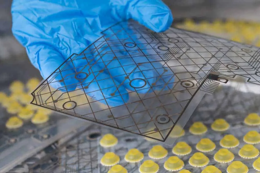
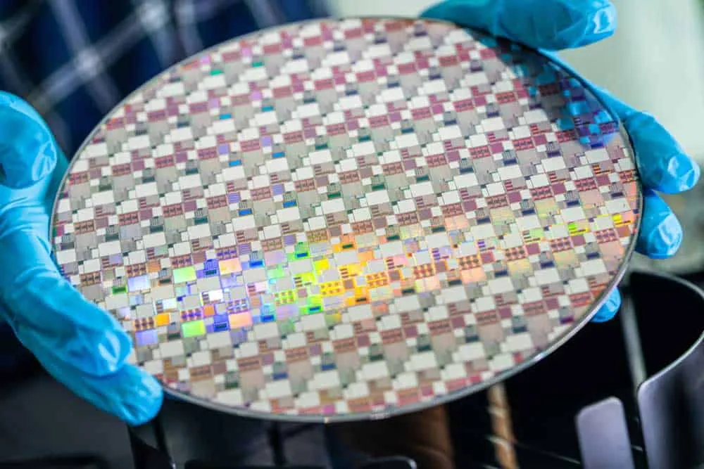
Material Preparation and Examination
The first step is to prepare the circuit board components and examine the solder pads on the board.
These board surfaces should be flat with silver, tin-lead, or gold-plated surfaces and zero holes.
Stencil Preparation
Solder Paste Printing
Using the appropriate stencil, apply the soldering paste using a squeegee. The application process can be automated (using a solder paste printer) or manual.
In assembly lines, mechanical clamps hold the PCBs and stencils, allowing the printing machine to apply the paste. This machine uses a squeegee to distribute the slurry above the entire surface to cover all apertures.
After that, it removes the stencil, leaving the soldering paste on the component pads. The manual application process follows a similar procedure, only without a machine.
Component Placement
The next step is to place the SMT electrical components above the solder paste on the pads. This component placement process occurs in a pick-and-place machine.
[Reflow Soldering](https://pcbinsider.com/wave-soldering-vs-reflow-soldering)
At this point, the components are sitting directly above the pads with a thin layer of soldering paste in between. And the only way to weld the two is by melting the solder balls in the paste.
So the circuit boards move along the conveyor belt to a reflow oven. This machine has four zones.
- - Preheat zone: This zone raises the board and component temperature gradually at about 1-2°C/second until 140-160°C. So the board should be here for about 2-3 minutes.
- Soak zone: In this zone, the oven maintains the temperature around the boards at around 160° for 60-120 seconds. This heat activates the flux in the solder paste to begin oxide reduction on the solder pads and the component leads.
- Reflow zone: Temperature in this zone gets ramped up again at about 1-2°C/second to 210-230°C. These high temperatures melt the tin in the solder paste, creating a direct metal contact between the component lead and the solder pad. And the components stick above the solder pad because the surface tension of molten tin keeps them in place.
- Cooling zone: The welded board undergoes gradual cooling to solidify the metal and create solid mechanical joints. Although most manufacturers ignore the ramp-down rate, the typical cooling rate should be 4°C/second.
If you have a double-sided PCB, repeat the processes above from solder paste printing on the other side. And always begin soldering the side with fewer components, then work on the side with more parts.
Cleaning and Inspection
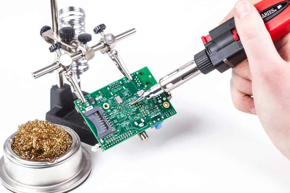
Clean the boards after they cool to room temperature, then inspect them to check the solder joint quality.
Typical inspection methods include electrical testing, In-Circuit Testing, flying probe, AOI, and X-ray. If you spot flaws, repair the defects immediately. You can rework these parts using manual soldering.
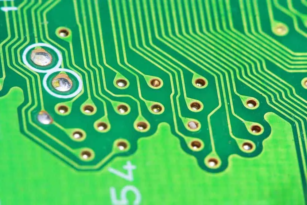
Through-Hole Technology (THT)
Through-hole technology is a component mounting process that involves attaching electric components with their leads penetrating the board.
These pieces are usually larger than their SMD counterparts and include parts like capacitors, transformers, and inductors.
The presence of holes alters the assembly process slightly because you can’t use reflow soldering. The molten tin will flow through the holes, leaving no joint after cooling. So the steps are as follows.
Material Preparation and Examination
Check the thru-hole components to ensure their pins are in one piece. Also, inspect the thru-holes to check their plating. There should be no visible plating defects.
Component Placement
You can insert these components using robots (in automated production lines) or manually.
Flux Application
Preheating
This step activates the flux to clean the board. Additionally, it helps prevent thermal shock by gradually raising the printed circuit board temperature.
Wave Soldering
At this point, the board has components mounted on one side and their pins protruding on the other side. It goes into a wave soldering machine, passing over a pan of molten solder.
The flux applied earlier ensures proper wetting from this wave. It is rare to get cold solder joints from this process because the molten solder is at the correct melting temperature.
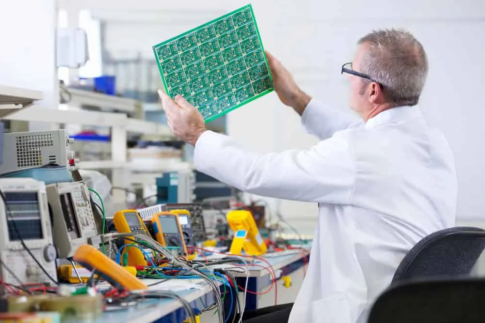
Cleaning and Inspection
After the entire board cools, do a visual inspection, functional and electrical reliability tests, automated optical inspection, etc.
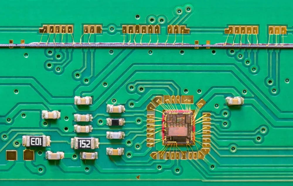
Mixed Assembly Technology
- - Material preparation and inspection
- Stencil preparation
- Solder paste printing
- Component placement
- Reflow process
- Inspection
- Through-hole component insertion
- Wave soldering (covers flux application and preheating)
- Cleaning and inspection
- Functional and continuity test checks (quality assurance)
Functional testing checks the PCBA functionality by simulating the circuit’s operations in its application area.
The process monitors the circuit board’s electrical characteristics when analog and power supply signals move through the components.
What About Selective Soldering?
You might have spotted a flaw in the steps above when assembling a set of SMT and THT components. All looks good until the wave soldering process.
The SMT components assembled in the previous step undergo another heating process as the THT components undergo welding.
Although the temperature required for wave soldering is lower than reflowing, it can affect some solder joints.
And the worst-case scenario is that some components can get damaged. Picture having a PCB with SMT components mounted on both sides.
How will you solder the protruding leads with surface-mount parts on the underside?
So it is worth considering another soldering option to mount the THT components. Here is where selective soldering comes into play.
This soldering process involves using techniques like:
- - Laser selective soldering
- Mass selective dip solder fountain
- Selective aperture tooling over wave solder
- Miniature wave selective solder fountain
- Robotic soldering iron
- Induction soldering
It is worth noting that the process is slower than wave soldering and requires a complex setup. However, it introduces precision when assembling these two technologies and consumes less flux & solder.
Wrap Up
As you can see, the PCB assembly method differs based on the component mounting technology.
Most circuit boards nowadays utilize SMT and THT assembly technologies, which implies the most typically used soldering methods are reflow and selective. But the steps can change depending on the specific application.
That’s it for now. If you need professional PCB assembly services or want to explore our rapid prototyping options, contact us for a quote. We’ll be happy to help with your circuit board assembly needs.
Related Articles
Continue exploring similar topics
PCB Assembly Machine
So assemblers need high-tech PCB assembly machine to mount and weld components on the board to make the circuit function as required.
What Is First Article Inspection?
What is a first article inspection?
What is CNC Technology? Industrial Guide
Discover what CNC technology is and how computer numerical control revolutionizes manufacturing. Learn about CNC machining applications in electronics assembly and PCB production.
Ready to bring your PCB design to life?
Get an instant quote for your custom PCB fabrication and assembly needs.
Get Instant Quote