PCB vs. PCBA: What Is The Difference
PCB vs. PCBA: Understand the key differences between printed circuit boards and assembled boards. Learn when each term applies in electronics manufacturing.
Author's Insight
“Many first-time customers ask me whether to order PCB or PCBA. My advice: unless you have in-house SMT equipment and skilled technicians, always go with PCBA. The cost difference is minimal compared to the time and potential quality issues you'll face with DIY assembly. Professional assembly ensures consistent quality and faster time-to-market.”
— Hommer Zhao
Looking at the terms PCB vs. PCBA, the only difference is the letter A. This letter stands for assembly. And it is what separates the definition of the two boards.
Printed circuit boards and printed circuit board assemblies are critical parts of electrical devices. But one is a blank circuit board, while the other is a complete circuit. Let’s look at the two to see which is which.
What Is a PCB?
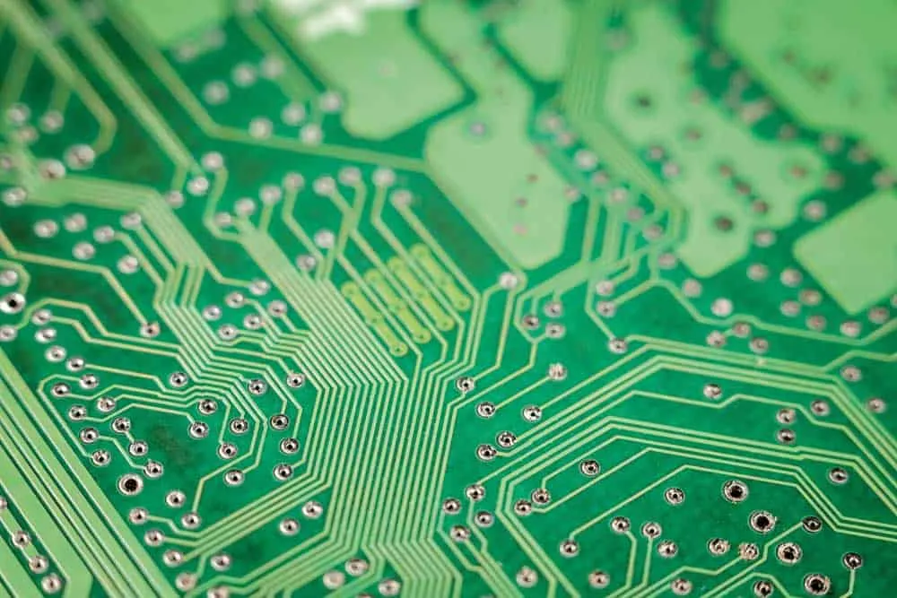
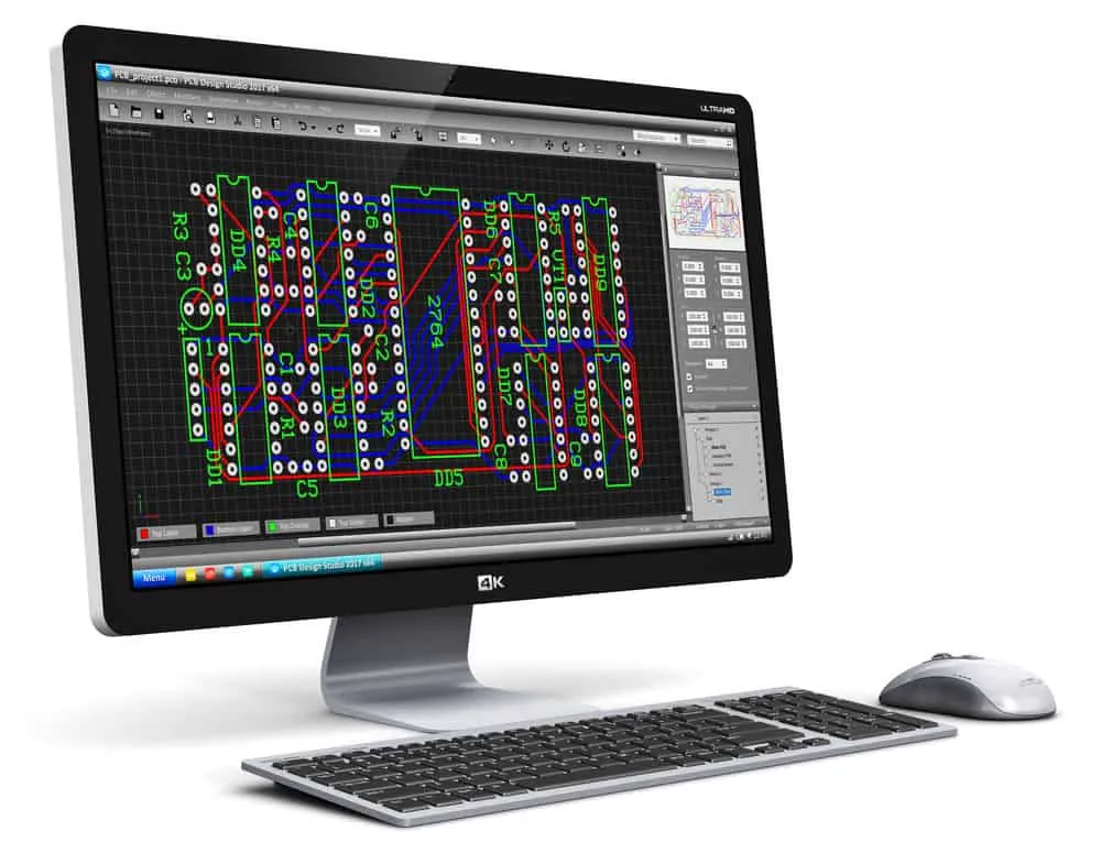
A Printed Circuit Board (PCB) is a compact wiring module used to connect electronic components. In its most basic form, a PCB has these four layers.
Core PCB Layers
Substrate Layer
The substrate is the base layer because it gives the printed circuit board its shape and structure. So it holds the other layers and components soldered on board. And it can consist of different materials, the most typical being FR4.
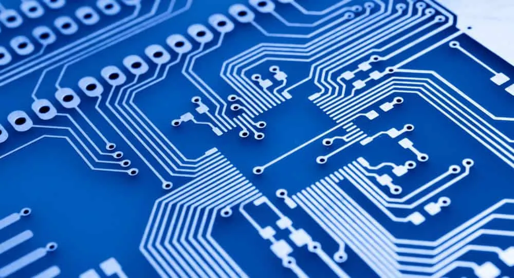
Copper Layer
Copper is one of the most conductive metals in the world. And PCBs have a copper foil layer placed and etched above the substrate to form the electrical connections. So these thin copper traces function as wires, enabling current flow between the electrical components.
Solder Mask Layer
Also known as the solder resist, the solder mask is an insulation layer that separates the copper layer from the:
- - Conductive items
- Solder
- Metal parts
So it protects the copper tracks to ensure only the required areas get exposed to the solder.
Also, this layer gives a PCB its color, which is green on most boards.
Most manufacturers use epoxy-acrylate or epoxy technology with a liquid photopolymer material to create this insulation layer.
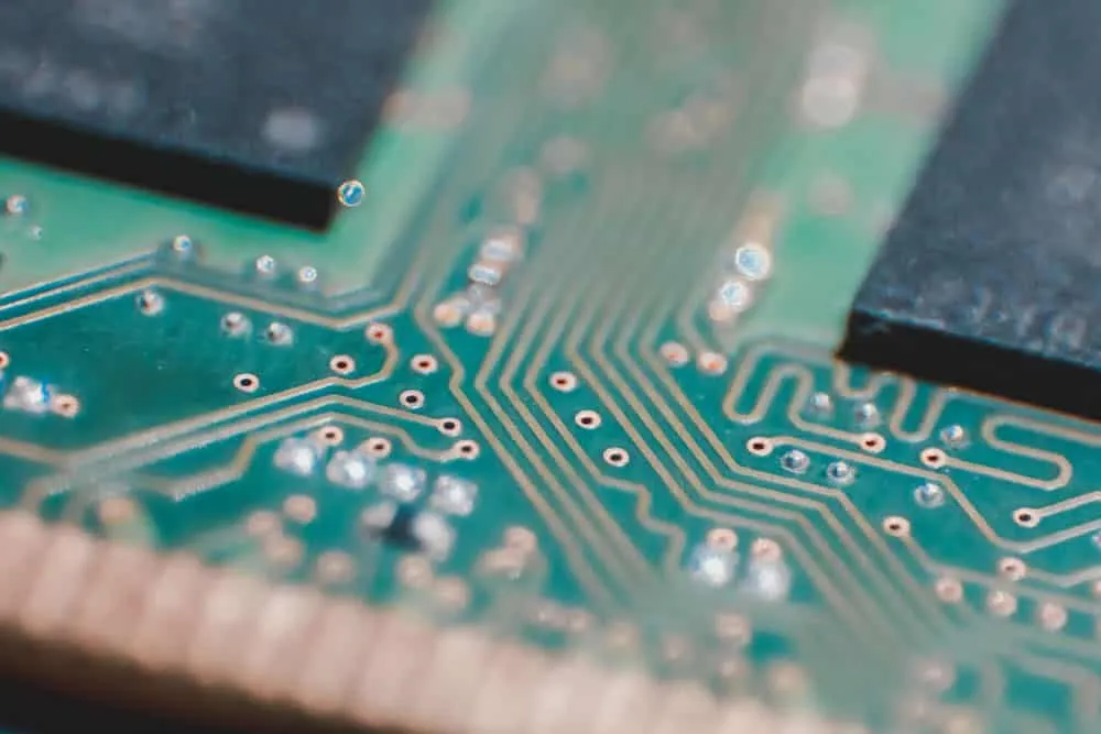
Silkscreen Layer
This layer does not contribute functionally to the PCB. Instead, it contains reference designator or component footprint markings that helps technical and engineering teams identify components.
Types of PCBs
Printed circuit boards come in different types that fall into three categories, depending on the substrate, frequency, and number of layers.
Substrate
Considering the substrate, PCBs come in these three types. Rigid Rigid printed circuit boards are solid and inflexible. So if you force or bend them out of shape, they will break.
The most typical material used to make the substrate layer in these boards is FR4.
But LED circuits have metal substrates to help dissipate heat.
So metal substrate boards have an extra insulation layer to prevent contact with the layer of copper. Flexible Flex PCBs contain either a thin insulating polymer film, Kapton (polyimide film), or a similar polymer as the substrate.
You can find these boards in keyboards and mobile phones (where the flexible PCB connects to the display).
Frequency
In the frequency category, circuit boards are available in two types. Low Frequency These boards have copper traces designed to handle low-speed, low-frequency signals.
Such signals are typical in projects dealing with control, reference voltage, analog power supply, and analog signal circuits. High Frequency These are the opposite of low-frequency boards because they can handle high-speed, high-frequency signals.
Modern electronic devices have high-frequency boards, especially if dealing with wireless networks.
Layers
Lastly, there is the layer category, which divides boards into three types. Single-Layer PCB Single-sided PCBs are the simplest, low-cost circuit boards because they only have one substrate and copper layer.
So the holes for mounting components don’t have to go all the way through.
Also, these electronic components sit on one side of this board. Double-Layer PCB A double-sided PCB has one substrate layer and two copper layers, one on either side.
So the board has a solder resist layer on both sides to insulate the layers of copper.
And it can have plated-through holes to connect the two conductive layers, with components mounted on both sides. Multi-Layer PCB What defines the layers is the copper traces. So this board has more than two conductive layers.
And it usually has multiple copper-plated holes to link the copper layers.
With a double-sided board, the substrate doubles up as the insulation between the two conductive materials.
But with multi-layer PCBs, you need prepregs to separate the rest of the copper layers. The core substrate can only be a single layer.
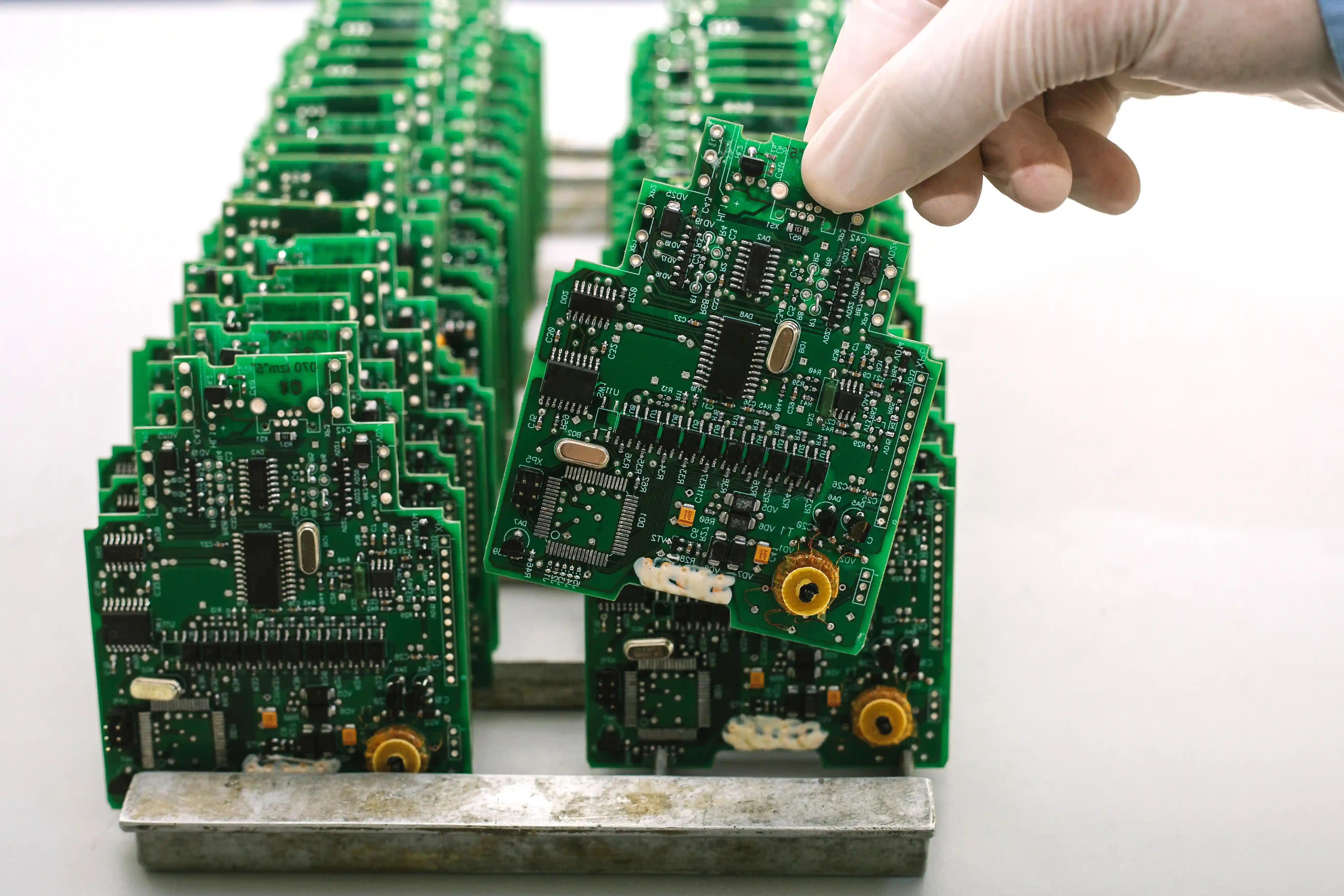
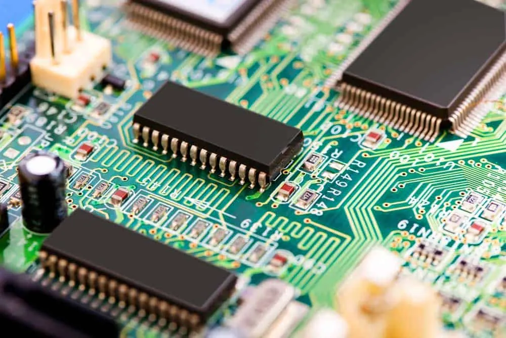
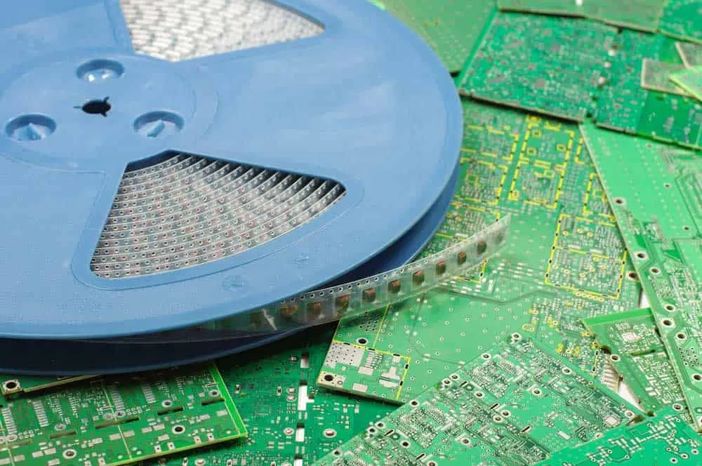
What Is a PCBA?
A Printed Circuit Board Assembly (PCBA) builds upon the PCB.
After fabricating the compact circuit into a board, the hardware is useless without electronic components.
So you have to mount passive and active components on it to achieve its function, creating a PCBA.
You can do the assembly manually, but it can take time, especially if the board has a high component density.
So we recommend getting your PCB manufacturer to complete the process by assembling the board. And the process usually entails the following.
- - Solder paste printing
- Component placement
- Wave soldering/reflow soldering
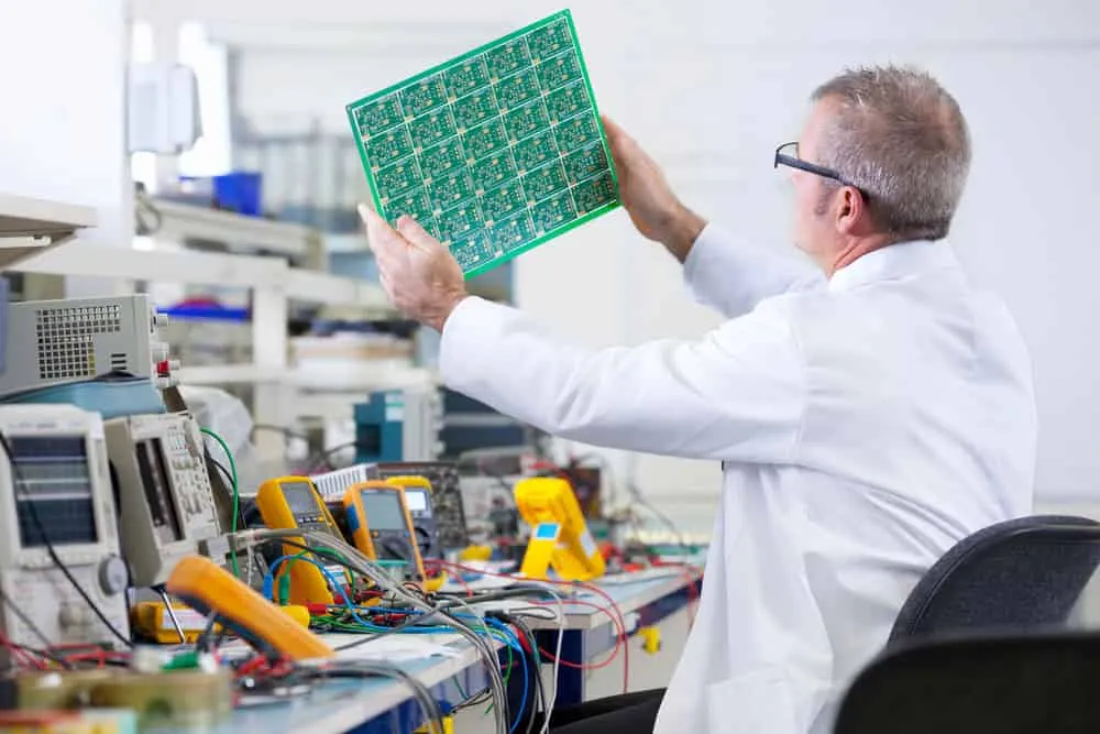
- Quality control inspection
PCB Assembly Methods
There are two technologies used to assemble PCB components.
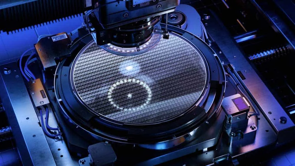
Surface-Mount Technology (SMT)
SMT is an assembly method that involves soldering surface-mount components on PCB pads.
These surface-mounted components have one advantage over their through-hole counterparts.
They are tiny. So the assembly ends up being more compact than when using through-hole parts.
The process of surface-mounted component soldering involves the following steps.
- - Applying solder paste to the leads
- Component placement
- Heating to melt the solder to bond after cooling (reflow soldering)
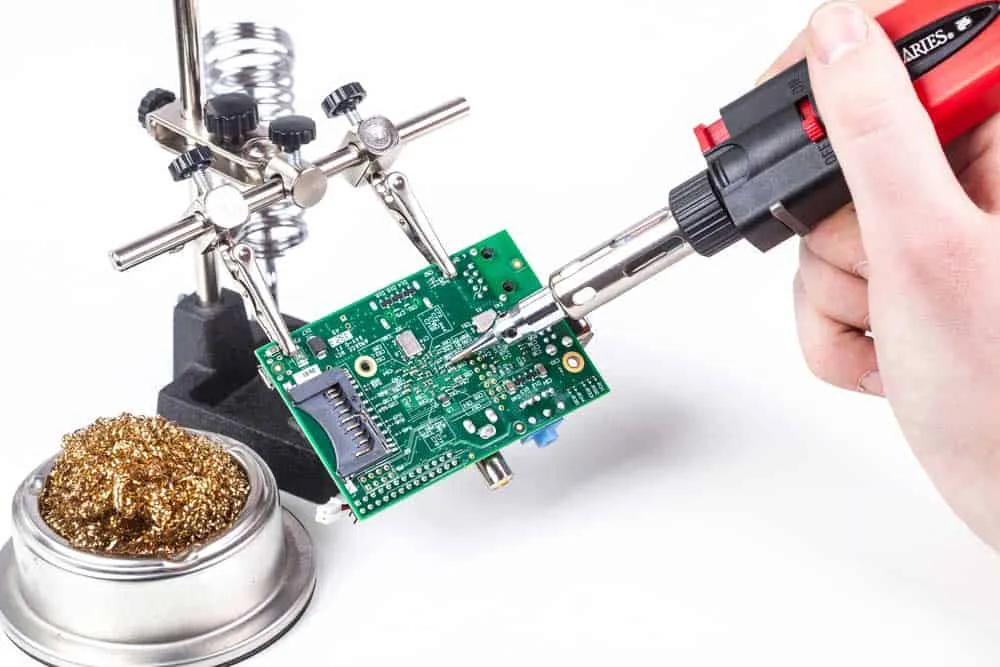
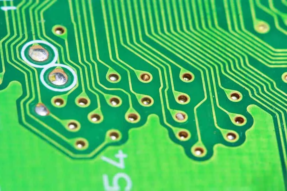
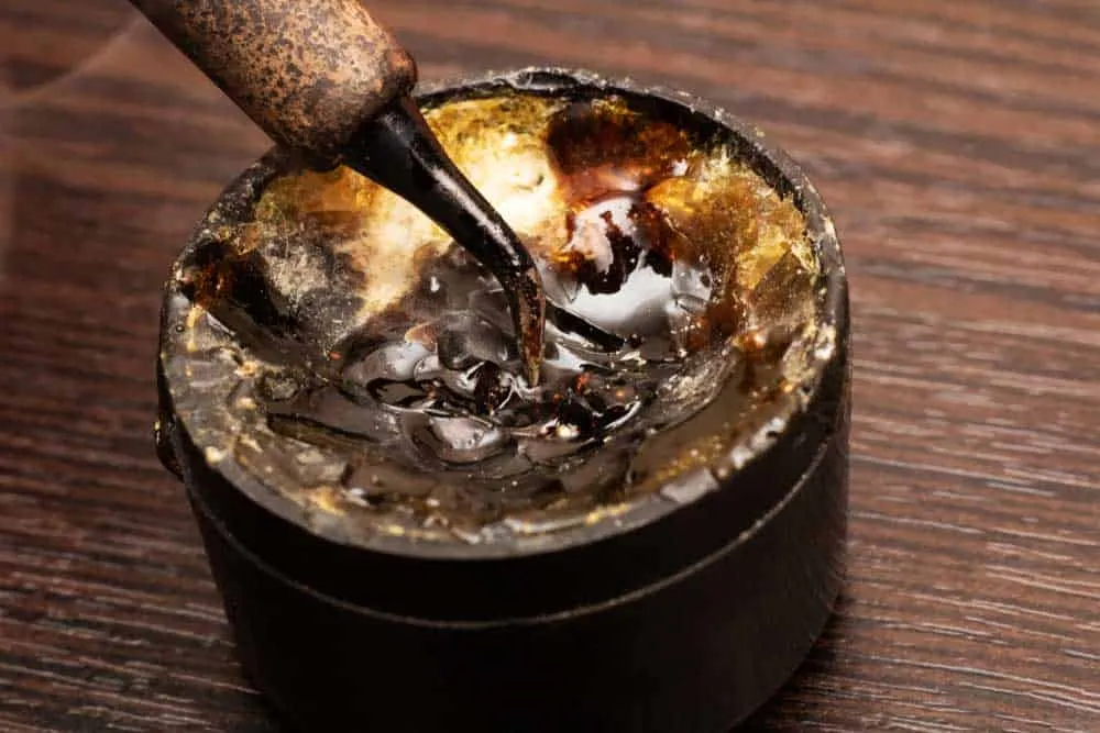
Through-Hole Technology (THT)
With thru-hole technology, you mount electronic components into holes drilled through the circuit board.
As stated earlier, THT components are larger than their SMT counterparts.
But their advantage is that they are cheaper, making them ideal for single-layer boards.
Mixed (SMT and THT)
After inspecting and testing the board, the through-hole components get inserted.
But it is impractical to use solder paste to mount these parts; the molten metal will melt through the holes.
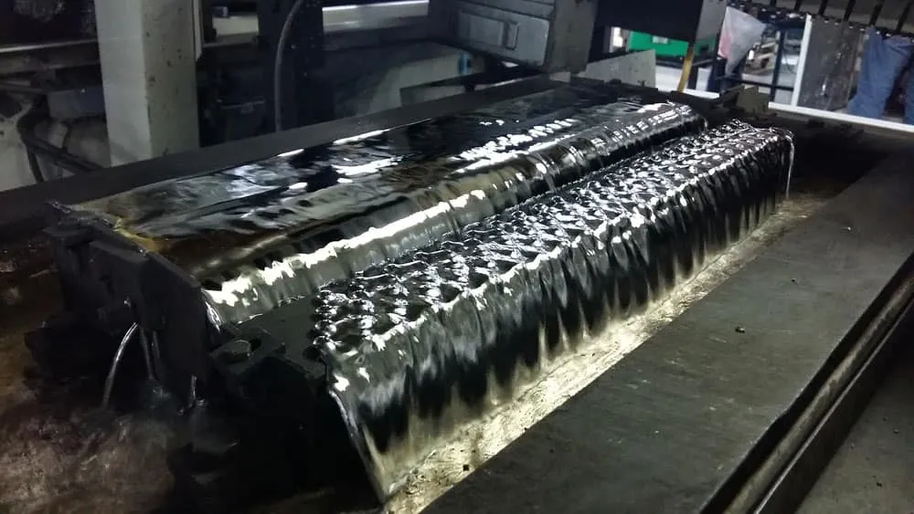
So the only way to attach these components is by manual or wave soldering.
The latter process is faster and involves running the boards through molten solder on a conveyor belt.
[Cost of PCB Assembly](https://pcbinsider.com/pcb-assembly-cost)
Getting a PCB fabricated is cheaper than a PCBA. With PCB assemblies, the extra assembly process introduces the following factors.
- - Labor costs
- Turnaround time
- Tooling charges
- Quantity
- Setup charges
- Component costs
- Shipping and packaging
- Additional quality control and inspection services
- Technology (SMT assembly is cheaper than THT because of the automated process)
But the assembly process is worth it because it saves time on your end. And remember, you need to have soldering knowledge and skills to do the process manually.
So although expensive, it usually makes economic sense to request a PCBA instead of a PCB.
PCB vs. PCBA: Functionality (Components)
A PCB is a blank board with zero components. So it is not a functional electrical device.
On the other hand, a PCBA contains all the parts that make it usable. So it is ready to use out of the box.
PCB vs. PCBA: Cost
The cost of fabricating a PCB is lower than the cost of building and assembling a circuit board.
As explained earlier, the factors arising from PCB assembly increase the overall cost significantly.
PCB vs. PCBA: Packaging
PCBs are flat, blank boards that usually get packaged using vacuum packaging.
But since the components soldered on printed circuit board assembly can get easily damaged, these boards must have special packaging.
In most cases, they come in anti-static or compartmental packaging. This safer packaging is one factor that increases the cost of PCBA.
PCB vs. PCBA: Manufacturing
From a manufacturer’s point of view, building PCBs is less challenging than making PCBAs because the process has no assembly.
So the turnaround time for PCBs is faster than that of PCBA.
Wrap Up
As you can see, the difference between a PCB and a PCBA is the component assembly process.
The former is a blank circuit board, while the latter is a complete, ready-to-use device.
Most PCB manufacturers can build and assemble these boards, so pick either option. But we recommend getting an assembled kit.
That’s it for this article. If you're ready to start your project, explore our PCB manufacturing services for bare boards or our complete assembly solutions for finished PCBAs. We hope it has been insightful; looking forward to your feedback in the comment section.
Related Articles
Continue exploring similar topics
Tinning Flux vs Regular Flux
Today, we provide insights into the tinning flux vs. regular flux debate. We aim to educate you on their benefits to any typical soldering process.
SMD vs. SMT vs. THT: PCB Comparison
This article is a comparison of SMD vs. SMT. vs. THT. If you have researched the PCB assembly processes, you must have encountered acronyms like SMD, SMT, and THT.
Allegro vs. Altium: PCB Software Guide
Allegro vs. Altium: Compare features, pros, cons, and pricing of these leading PCB design tools. Find out which software best fits your design needs.
Ready to bring your PCB design to life?
Get an instant quote for your custom PCB fabrication and assembly needs.
Get Instant Quote