Industrial PCB Guide: Design and Manufacturing for Harsh Environments
Complete guide to industrial PCB design and manufacturing. Learn about materials, standards, protective measures, and testing for reliable harsh environment operation.
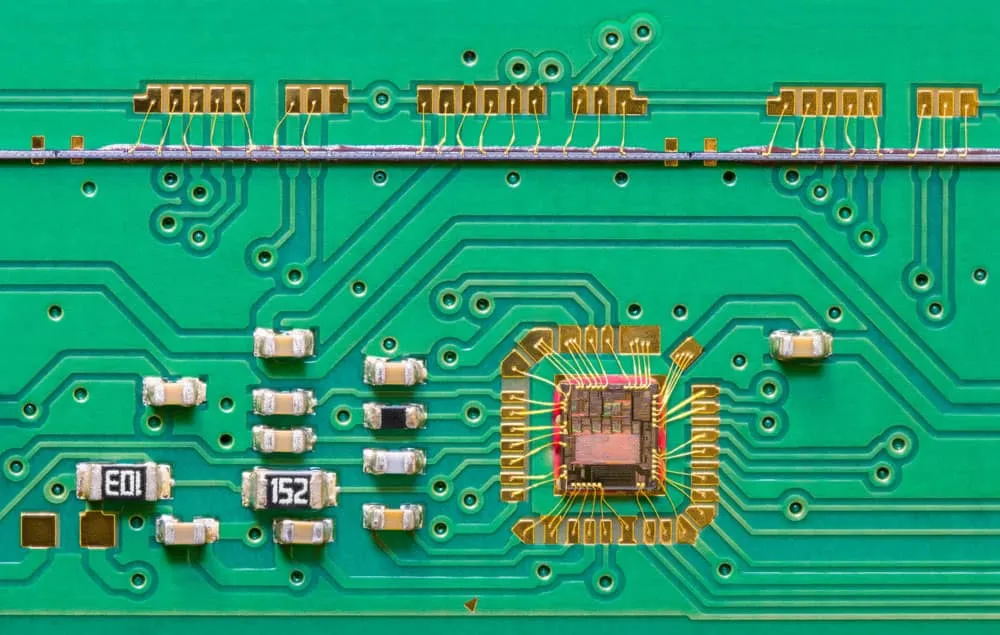
Industrial printed circuit boards operate reliably in demanding environments for extended periods, typically 10-15+ years of near-continuous operation. Unlike commercial-grade boards, industrial PCBs withstand punishing temperature swings, shock, vibration, humidity, and chemical exposure. This comprehensive guide covers design standards, materials, protective measures, and manufacturing practices enabling long-lasting, rugged circuit boards.
What Defines Industrial PCBs?
Industrial PCBs differentiate from commercial boards across several key dimensions:
Operating Environments: Designed for extreme industrial settings with wider temperature ranges (-40°C to 125°C or beyond), shock and vibration exposure, humidity extremes, and chemical contamination resistance.
Extended Lifespan: Engineered for high reliability over long product field life, often 10-20 years of operation in demanding conditions. Consumer electronics may target 3-5 year lifespans, while industrial equipment expects decades.
Criticality: High availability, functionality, and safety criticality when PCBs fail. Entire industrial systems may depend on circuit board reliability. Downtime costs in industrial settings often exceed equipment replacement costs.
Rigorous Standards: Must conform to stringent design, manufacturing, and testing standards ensuring consistent quality and documented performance.
Industrial PCB Applications
Electronics requiring specially designed industrial-class PCBs include:
- - Motor drives and industrial controllers
- Power supplies and battery chargers
- Process transmitters and remote terminal units
- Railway and transportation electronics
- Downhole drilling tools and mining equipment
- Aerospace avionics systems
- Military vehicle electronics and naval systems
- Factory automation controllers
- Energy management and power distribution
- Medical diagnostic equipment
Ruggedness, extended lifespan, and high reliability distinguish industrial PCBs even though they may visually resemble commercial boards.
Industrial PCB Design Standards
IPC Class 3
Issued under IPC-2221 standards, Class 3 covers performance requirements for industrial electronics printed boards including:
- - Temperature cycling (-65°C to 150°C)
- Vibration (10-500Hz at 10G+)
- Mechanical shock of 100-1500G
- Moisture resistance testing
- Other environmental stresses
Additionally specifies recommended test methods, quality conformance criteria, and inspection details for qualifying Class 3 boards. Represents minimum level for most industrial applications.
IPC-6012 Automotive Electronics
Performance standards tailored for automotive and transportation applications covering:
- - Temperature ranges (-40°C to +125°C)
- Rapid humidity transitions
- Vibration profiles matching vehicle environments
- Test schedules and inspection criteria
- Qualification maintenance requirements
Contains Class 1, 2, and 3 acceptance levels with Class 3 most demanding.
IPC-A-610 Acceptability Standard
Visual defect criteria focused on workmanship, component orientation, soldering quality, part types, and surface finishes. Used globally across PCB types to determine quality through manufacturing and acceptance inspection. All boards should pass IPC-A-610 for ship readiness.
IEC-61188
International guidelines covering printed board layout, stackup, material properties, electrical test methods, environmental stress testing, and production traceability. Notable for temperature/humidity cycling, mixed flowing gas corrosion testing, and chemical resistance requirements.
UL 796
Underwriters Laboratory standard including flame resistance, temperature indexing tests, electrical testing, and construction methods. Special UL 796 File Number recognition requires passing safety-focused design evaluations applicable for power electronics seeking UL listing.
Materials for Industrial PCBs
Substrate Materials
| Material | Properties | Applications | |----------|------------|-------------| | FR-4 Glass Epoxy | Low cost, moderate performance | Mild industrial environments | | High-Tg FR-4 | Increased heat resistance (Tg 170-180°C) | Power electronics, automotive | | Polyimide | Extreme temperature range (-200°C to +260°C) | Downhole, space, aviation | | IMS (Insulated Metal Substrate) | Excellent thermal conductivity | LEDs, power devices | | Ceramic | High frequency, extreme temperature | RF/microwave, harsh environments | | Metal Core | Superior heat dissipation | High-power applications |
Standard FR-4 materials with Tg around 130-140°C prove insufficient for harsh environments. High-Tg FR-4 (170-180°C) suits industrial and automotive applications where operating temperatures reach 105-130°C, providing better dimensional stability and reduced delamination risk.
Copper Weight Considerations
Industrial applications often require heavier copper:
- - Standard (1oz): Suitable for signal traces in moderate applications
- Heavy (2oz): Recommended for current-carrying paths reducing resistance and heat
- Extra Heavy (3-6oz): High-power designs requiring maximum current capacity
Thicker copper reduces electrical resistance, runs cooler, and provides physical strength while spreading heat from hot spots.
Special Layer Constructions
- - Extra thick copper (>2oz) for high-current paths
- Impedance control layers for signal integrity
- Buried and blind vias for HDI density
- Flood/plane layers for EMI shielding
- Graphite layers for thermal spreading
- Double-sided boards for shock/vibration damping
Protective Measures
Conformal Coating
Thin polymeric films applied to assembled PCBs shield against environmental damage. Coating thickness typically ranges 25-75 micrometers depending on severity.
Coating Types:
- - Acrylic: Easy to apply and rework, good moisture resistance for moderate environments
- Silicone: Highly flexible and heat-resistant up to 200°C, ideal for temperature extremes
- Polyurethane: Excellent chemical resistance for harsh industrial settings with solvent exposure
- Parylene: Vapor-deposited coating providing superior protection, though harder to apply and remove
Encapsulation and Potting
Complete PCB encapsulation in protective resins provides extreme protection against toxic gases, corrosive fluids, and severe vibration. Encapsulation materials must be electrically insulating and thermally conductive while blocking environmental threats.
Edge Plating and Connectors
Reinforced gold or tin-lead edge connector fingers withstand 10,000+ mating cycles required for industrial equipment serviced over decades.
Industrial PCB Design Practices
Simulation and Analysis
Extensive electrical, thermal, and vibration modeling using tools like ANSYS or COMSOL predicts responses and identifies resonances before building prototypes. Early simulation spots problems avoiding costly re-spins.
Component Derating
Derating guidelines lower actual operating values below datasheet absolute maximums for voltage, current, and power. Provides margin against parameter drift over extended field life. Typical derating ranges 50-80% of maximum ratings.
Redundancy Design
Extra backup pathways, traces, and connections with automated failover capability prevent single points of failure. Critical circuits may include duplicate components or paths ensuring continued operation despite component failures.
Layout Techniques
- - Thermal management through copper pours and thermal vias
- Stitching vias for ground plane integrity
- Edge control structures for EMI containment
- Wide, thick conductors handling vibration and currents
- Component placement minimizing thermal stress
DFM Analysis
Rigorous design analysis checks manufacturability issues around thermal relief connections, trace widths, annular rings, and other fabrication-critical parameters. Getting layout right initially avoids costly revisions.
Standards Validation
Testing conformity with relevant standards like MIL-PRF-31032, IPC Class 3, or industry-specific requirements qualifies designs before production release.
Manufacturing and Quality Control
Process Controls
- - Cleanroom environments preventing contamination
- Six Sigma process controls across 35+ fabrication steps
- MES, ERP, and MRP systems coordinating workflow
- Machine interfaces enabling automated inspection and testing
Testing Requirements
Harsh environment PCBs require 3-5x more rigorous testing than consumer-grade boards:
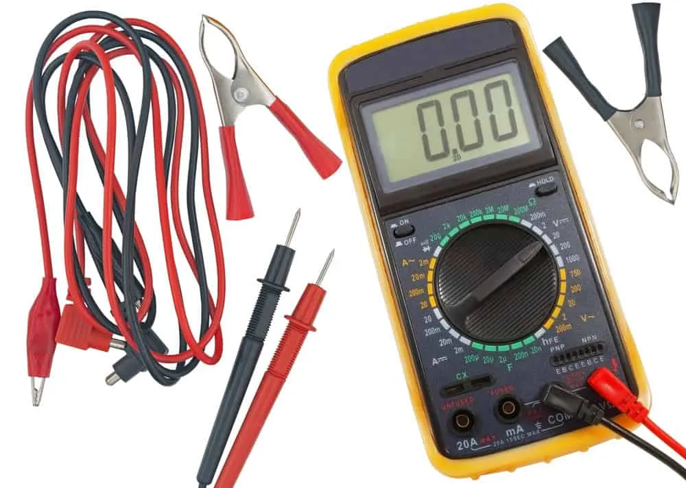
- - ICT (In-Circuit Test): Finds shorts and opens across all nodes
- Flying Probe: Checks nodes inaccessible to bed-of-nails fixtures
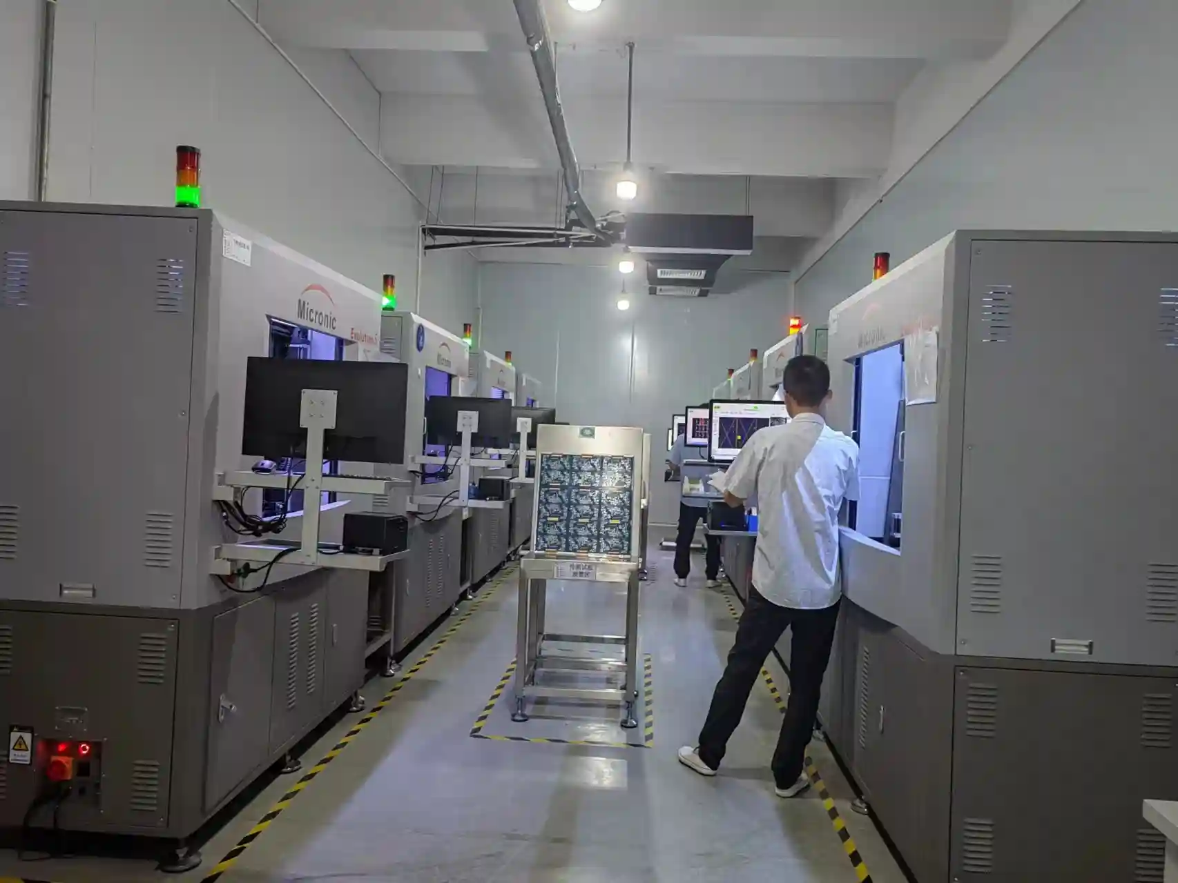
- AOI (Automated Optical Inspection): Inspects visual defects
- X-Ray Inspection: Confirms inner layer detail and hidden joints
- Thermal Cycling: 1,000+ cycles from -40°C to 85°C simulating temperature extremes
- Vibration Testing: Frequencies up to 2000Hz mimicking industrial machinery
- Humidity Testing: 85% RH for 1000+ hours
- Salt Spray: 500+ hours exposure for corrosive environments
Quality Certifications
Key certifications for industrial PCB manufacturers:
- - ISO 9001:2015: Quality management systems
- IATF 16949: Automotive quality management
- ISO 14001:2015: Environmental management
- ANSI/ESD S20.20: Electrostatic discharge control
- IPC Validated: Fabrication conforming to IPC standards
- ITAR Registration: Required for defense/aerospace PCBs
Documentation Requirements
- Full archive packs for each board including:
- Photomicrographs of construction
- Electrical test results
- Corrective action reports
- Material certifications and traceability
- Process parameter records
Cost Considerations
Harsh environment PCBs cost 2-5x more than standard boards due to specialized materials and extensive testing. However, 5-10x longer lifespan makes them cost-effective for critical applications where downtime or failure costs far exceed PCB premiums.
Selecting an Industrial PCB Partner
Essential Capabilities
- - Years of experience specifically with industrial customers
- Wide material expertise including ceramic, IMS, flex-rigid, and metal core
- Design for Excellence services aiding product development
- Staff engineers validating layouts to relevant standards
- Global quality certifications and standards alignment (ISO, IATF 16949, IPC)
Key Questions
- - How is proprietary customer data protected?
- What DFM optimization methods and Gerber analysis are performed?
- What standard testing and inspection processes apply?
- Are qualification reports provided with deliverables?
- What inventory and obsolescence management programs exist?
- What counterfeit part avoidance controls are implemented?
Summary
Industrial electronics demand PCB reliability well beyond commercial boards to perform properly for decades across extreme environments and safety-critical applications. Designing to rigorous standards through simulation, analysis, derating, and redundancy while partnering with certified manufacturing facilities ensures products meet customer expectations in harshest conditions. Specialized materials, extensive testing, and documented qualification processes deliver confidence for successful field deployment.
For industrial PCB manufacturing meeting the most demanding requirements, contact WellPCB for expert guidance and precision manufacturing services.
Frequently Asked Questions
What applications use industrial-class PCBs?
Typical applications include transportation power systems, factory automation controllers, energy management products, remote telemetry units, military vehicle computing, aerospace avionics, downhole drilling tools, and similar electronics requiring high reliability over 10-20+ years of field operation.
How do industrial PCBs differ from commercial PCBs?
Industrial PCBs support wider operating temperatures (-65°C to +150°C), longer deployment lifetimes (10-20 years), survival through harsh vibration/shock/moisture, high availability requirements (>99%), rigorous testing and qualification, and precision manufacturing with full traceability.
What certifications should industrial PCB manufacturers have?
Look for ISO 9001:2015 (quality management), IATF 16949 (automotive), ISO 14001 (environmental), ANSI/ESD S20.20 (ESD control), documented high-reliability controls for aerospace work, and IPC validation for fabrication standards. ITAR registration is required for defense and aerospace applications.
Why is FR-4 still used for industrial PCBs?
While polyimides and ceramics handle wider temperature swings, high-Tg FR-4 versions (170-180°C) work for many industrial applications at lower cost with better fabricator familiarity. FR-4 remains viable when temperatures don't reach extreme levels.
What protective coatings suit industrial PCBs?
Conformal coatings including silicone (temperature extremes), polyurethane (chemical resistance), and acrylic (general protection) shield assembled boards. For severe environments, complete encapsulation in protective resins provides maximum protection against moisture, chemicals, and mechanical stress.
Related Articles
Continue exploring similar topics
AOI Testing Guide: PCB Automated Optical Inspection Explained
Complete guide to Automated Optical Inspection (AOI) for PCB manufacturing. Learn how AOI works, defect detection capabilities, 2D vs 3D systems, and implementation best practices.
Bed of Nails Test Fixture Guide: PCB In-Circuit Testing Explained
Complete guide to bed of nails test fixtures for PCB testing. Learn about fixture types, pogo pins, ICT procedures, and quality control applications.
Double-Sided PCB: Complete Design and Manufacturing Guide
Master double-sided PCB design with our comprehensive guide covering manufacturing processes, layout strategies, via specifications, and cost optimization tips.
Ready to bring your PCB design to life?
Get an instant quote for your custom PCB fabrication and assembly needs.
Get Instant Quote