Bed of Nails Test Fixture Guide: PCB In-Circuit Testing Explained
Complete guide to bed of nails test fixtures for PCB testing. Learn about fixture types, pogo pins, ICT procedures, and quality control applications.
Bed of nails test fixtures remain essential tools for PCB quality control, enabling rapid validation of assembled circuit boards before shipment to customers. These fixtures use arrays of spring-loaded pogo pins to simultaneously contact hundreds or even thousands of test points, checking for manufacturing defects and verifying proper circuit functionality. Understanding bed of nails testing helps engineers implement effective quality control processes.
What is a Bed of Nails Test Fixture?
A bed of nails test fixture is an electronic testing apparatus containing an array of spring-loaded pogo pins aligned to make electrical contact with test points on printed circuit boards. Named by analogy with an actual bed of nails, these devices provide reliable simultaneous connection with hundreds or thousands of individual test nodes by pressing the device under test (DUT) down onto the pin array.
The pins insert into holes in laminated fixture plates, aligned using tooling pins to precisely contact designated test points on PCBs. Wires connect each pin to measuring equipment that orchestrates testing sequences, validates circuits, and reports pass/fail results. This approach dramatically accelerates testing compared to manual probing or sequential test methods.
Bed of nails fixtures serve as critical quality gates in PCB assembly lines, catching manufacturing defects before products reach customers. The technology enables comprehensive in-circuit testing (ICT) that validates component values, checks for opens and shorts, and verifies circuit functionality—all within seconds per board.
How Bed of Nails Testing Works
Test Procedure Overview
The testing process follows a systematic sequence ensuring consistent, reliable results:
- 1. Fixture Programming
- Import PCB CAD data to map test point locations
- Configure pogo pin positions matching board layout
- Define test protocols specifying checks and acceptance criteria
- Program test equipment with board-specific routines
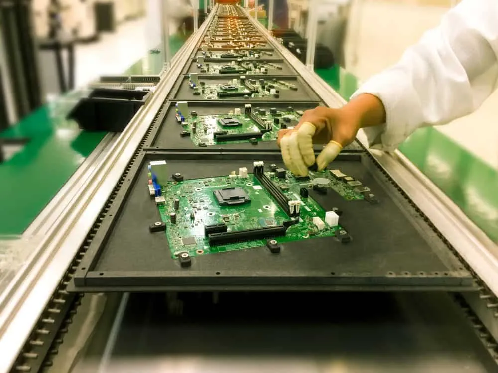
- 2. PCB Loading
- Position assembled board onto fixture alignment pins
- Activate hold-down mechanism (vacuum, mechanical, or manual)
- Compress board onto pogo pin array establishing contact
- Verify adequate contact pressure across all test points
- 3. Test Execution
- Execute programmed test sequence automatically
- Measure electrical parameters at each test node
- Compare readings against specified tolerances
- Log pass/fail status for each check point
- 4. Results and Unloading
- Display overall pass/fail determination
- Generate detailed test reports for failed boards
- Release hold-down mechanism
- Remove board and check for pin contact impressions
What Gets Tested
Bed of nails fixtures enable comprehensive PCB validation:
Opens Detection: Infinite resistance readings indicate broken traces, damaged vias, or missing solder connections that would prevent circuit operation.
Shorts Detection: Near-zero resistance between nodes that should be isolated reveals solder bridges, contamination, or design errors causing unintended connections.
Component Values: In-circuit measurements verify resistors, capacitors, and inductors fall within specified tolerances, catching wrong components or failed parts.
Diode/Transistor Tests: Forward voltage drops and gain measurements confirm semiconductor components function correctly.
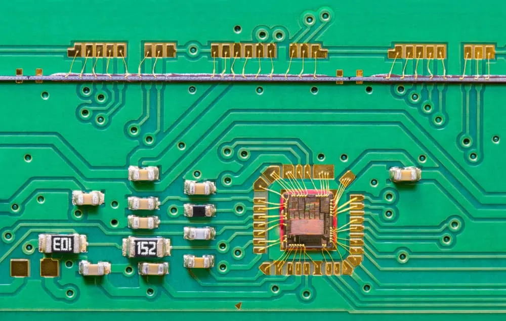
IC Connectivity: Verify integrated circuit pins connect properly to board traces without opens or shorts.
Power Distribution: Check power rail continuity and isolation from ground planes.
Fixture Types and Configurations

Vacuum Fixtures
Vacuum fixtures use air pressure differential to pull PCBs firmly onto pogo pin arrays. This approach provides consistent, repeatable contact pressure across all test points. Vacuum fixtures deliver superior signal quality compared to mechanical alternatives but cost more due to manufacturing complexity. High-volume production lines favor vacuum fixtures for their reliability and throughput.
Pneumatic Press-Down Fixtures
Pneumatic systems use compressed air to press PCBs onto test pins from above. These fixtures offer good automation compatibility and consistent pressure application. Lower cost than vacuum alternatives makes pneumatic fixtures popular for medium-volume testing requirements.
Manual Fixtures
For low-volume production or prototype testing, manual fixtures provide cost-effective solutions. Operators place PCBs into fixtures and apply pressure manually or with simple mechanical assists. While lacking automation speed, manual fixtures offer flexibility and minimal setup investment for smaller operations.
Clamshell Fixtures
Clamshell designs utilize hinged top and bottom pin plates that close over PCBs like clamping cradles. This configuration enables simultaneous access to both board sides—essential for double-sided assemblies where test points exist on top and bottom surfaces.
Flying Probe Hybrids
Some fixtures integrate movable probes on X-Y axes alongside fixed pogo pins. Flying probes reach difficult test nodes impractical for fixed pin positions, combining bed of nails speed with flying probe flexibility. This hybrid approach maximizes test coverage on complex boards.
Pogo Pin Specifications
Critical Parameters
Pogo pin selection significantly impacts fixture performance:
Pitch: Vertical spacing between pins determines how closely test points can be accessed. Common pitches include 100-mil (2.54mm), 75-mil, and 50-mil for denser boards. Finer pitches require higher precision fixtures.
Travel: Compressive stroke length accommodates board thickness variations and ensures adequate contact pressure. Typical travel ranges from 2-4mm depending on application requirements.
Current Rating: Maximum electrical current the pin safely carries affects power circuit testing capability. Standard pins handle 2-3A while high-current variants support 10A+ for power testing.
Spring Force: Contact force ensuring reliable connections typically ranges 50-200 grams. Higher forces improve contact reliability but increase total fixture force requirements.
- Tip Style: Different tip configurations suit specific applications:
- Cone tips mate with via holes or directly contact PCB tracks
- Single pointed tips penetrate oxide films on solder joints
- Multi-pointed tips connect through larger solder areas
- Flat tips suit clean pad surfaces
Pin Quality Considerations
Premium pogo pins feature precision machining, gold plating for corrosion resistance, and hardened materials for extended cycle life. Quality pins typically withstand 100,000+ compression cycles before requiring replacement. Investing in superior pins reduces maintenance burden and false failure rates.
Fixture Design Considerations
Test Point Guidelines
Effective bed of nails testing requires proper PCB design accommodation:
Pad Size: Test pad diameters should measure 0.015" to 0.040" (nominally 0.035") for standard probes. Larger pads provide more reliable contact while smaller pads enable denser test coverage.
Component Clearance: Test pads should maintain minimum 0.1" spacing from tall components (>0.35") to prevent probe damage and avoid shorts. Tall components may require fixture milling for clearance.
Accessibility: Both board sides may need test access for comprehensive coverage. Plan test point placement considering fixture configuration limitations.
Via Testing: Filled or tented vias may prevent probe contact. Specify via treatment compatible with testing requirements.
Custom vs. Standard Fixtures
Standard grid array fixtures work well for boards with regularly spaced test points. Custom fixtures with application-specific pin layouts optimize coverage for unique board geometries and component placements. Development costs increase for custom fixtures but test coverage improves for complex designs.
Applications of Bed of Nails Testing
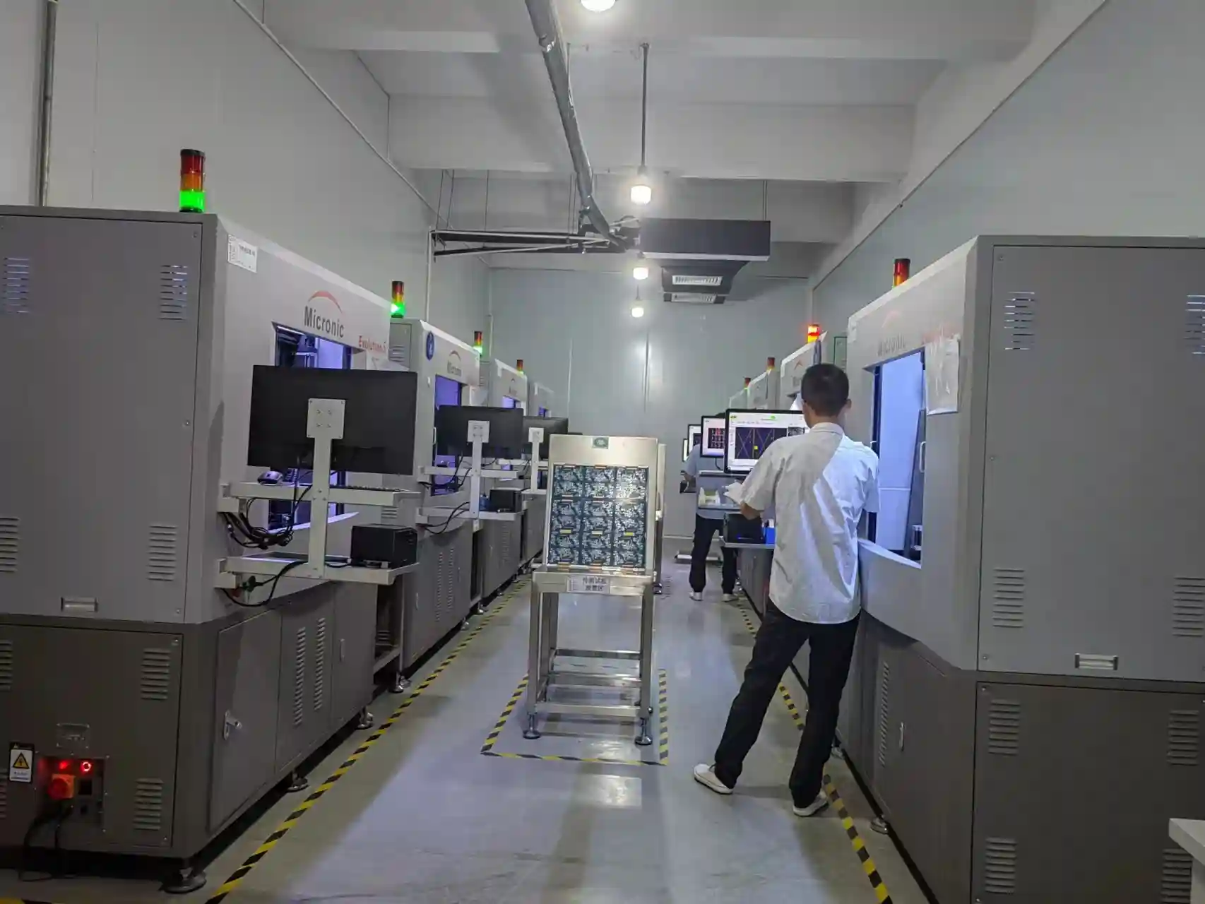
End-of-Line Quality Control
Most commonly, bed of nails fixtures serve as critical quality gates in PCB assembly lines. Every assembled board passes through testing before shipment, catching manufacturing defects that would cause field failures. Rapid test execution maintains production throughput while ensuring quality.
Design Verification
During PCB prototyping and design verification, bed of nails testing validates that circuits meet specifications. Engineers quickly identify design issues or assembly problems requiring correction before production release.
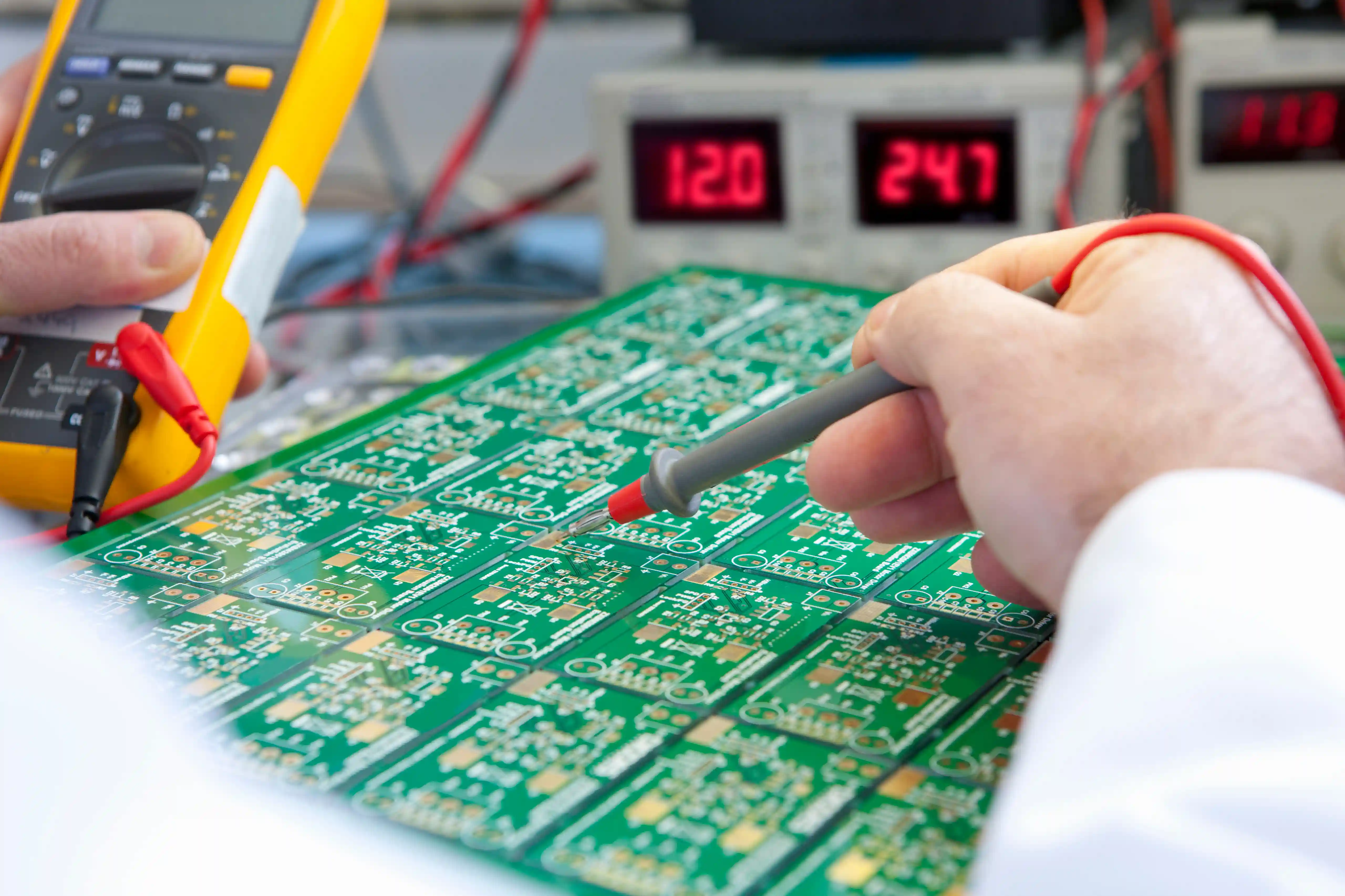
Troubleshooting and Debugging
Faulty boards pulled from production or returned from field failures undergo diagnostic testing to identify root causes. Bed of nails access to multiple test nodes accelerates fault isolation compared to manual probing.
Incoming Inspection
Some manufacturers test purchased PCB assemblies upon receipt, verifying supplier quality before integration into products. Bed of nails testing provides rapid incoming inspection capability.
Production Sampling
Statistical process control programs may sample production runs for detailed testing. Bed of nails fixtures enable thorough validation of sample boards checking for process drift.
Advantages of Bed of Nails Testing
Speed and Efficiency
Simultaneous contact with hundreds of test points enables parallel testing completing in seconds per board. This speed supports high-volume production without creating testing bottlenecks.
Comprehensive Coverage
Unlike methods accessing limited nodes, bed of nails fixtures can contact almost every testable point on a PCB. Extensive coverage catches defects that selective testing might miss.
Repeatable Results
Fixture alignment and automated test execution deliver consistent results across operators and shifts. Repeatable testing enables meaningful quality metrics and trend analysis.
Scalable Solutions
Small "micro" fixtures with minimal pin arrays suit simple boards at low cost. Standard plates scale to accommodate complex designs with thousands of test points. Fixture complexity matches application requirements.
Functional Validation
Beyond detecting electrical faults, bed of nails testing exercises circuits with test patterns verifying intended functionality. Boards receive comprehensive validation before shipment.
Challenges and Limitations
Dense Board Access
Boards with components on both sides or very fine-pitch devices can create test point access difficulties. Flying probe hybrids help reach challenging nodes that fixed pins cannot contact.
Contact Intermittency
Insufficient pogo pin stroke, inadequate force, or worn pins may cause occasional open readings during testing. Regular fixture maintenance and calibration minimize false failures.
Dense Pin Field Shorts
Very fine pitch pin arrangements risk shorts between neighboring pins. Proper insulation and careful fixture design prevent this issue.
Custom Development Costs
Application-specific fixtures with unique pin layouts and test programs require development investment. These costs may be significant for complex or frequently changing designs.
Maintenance Requirements
Fixtures demand regular inspection for pin wear, cleaning to maintain contact reliability, and periodic calibration. Ongoing diligence prevents degraded test quality over time.
Summary
Bed of nails test fixtures remain indispensable for PCB quality control, delivering the speed, coverage, and reliability production testing demands. Understanding fixture types, pogo pin specifications, and design considerations helps engineers implement effective testing strategies. While challenges exist for dense or complex boards, bed of nails technology continues evolving to meet modern PCB testing requirements.
For PCB assembly with comprehensive testing services, contact WellPCB for quality solutions including in-circuit testing and functional validation.
Frequently Asked Questions
How does bed of nails PCB testing work?
An array of spring-loaded pogo pins embedded in a fixture plate makes electrical connections when a PCB under test is pressed onto the array. Test equipment sends signals through the pins into circuits, measuring responses to detect faults and verify functionality. Testing completes in seconds as all points connect simultaneously.
What materials are bed of nails fixtures made from?
Fixture plates typically use aluminum, plastics, or epoxy-glass laminates capable of withstanding repeated compressions without warping. Pogo pins utilize beryllium copper alloys with gold plating for electrical conductivity and corrosion resistance.
How often do bed of nails fixtures need maintenance?
Fixtures require regular inspection of pins for wear, periodic cleaning to ensure reliable contact, and occasional calibration adjustments. Pogo pins typically withstand 100,000+ compression cycles before needing replacement. Maintenance frequency depends on usage intensity.
What is the difference between ICT and functional testing?
In-circuit testing (ICT) using bed of nails fixtures validates individual components and connections—checking resistor values, detecting shorts, verifying traces. Functional testing exercises complete circuits to confirm the board operates as designed. Many test strategies combine both approaches.
Can bed of nails test both sides of a PCB?
Clamshell fixtures with pogo pins on both top and bottom plates access test points on both board sides simultaneously. Single-sided fixtures only contact one surface, requiring flip testing or flying probes for double-sided access.
Related Articles
Continue exploring similar topics
AOI Testing Guide: PCB Automated Optical Inspection Explained
Complete guide to Automated Optical Inspection (AOI) for PCB manufacturing. Learn how AOI works, defect detection capabilities, 2D vs 3D systems, and implementation best practices.
Double-Sided PCB: Complete Design and Manufacturing Guide
Master double-sided PCB design with our comprehensive guide covering manufacturing processes, layout strategies, via specifications, and cost optimization tips.
Electronics Manufacturing Services (EMS): Complete Outsourcing Guide
Comprehensive guide to EMS providers covering outsourcing benefits, selection criteria, service offerings, and industry trends for 2025.
Ready to bring your PCB design to life?
Get an instant quote for your custom PCB fabrication and assembly needs.
Get Instant Quote