
FPC Flexible Printed Circuit Guide: Design, Materials & Applications
Complete guide to flexible printed circuits (FPC). Learn about materials, design principles, manufacturing processes, and applications for flex PCBs.
The global flexible printed circuit board market exceeded $16.2 billion in 2024 and continues growing at 11.5% annually, driven by demand for thinner, lighter, and more reliable electronic devices. From foldable smartphones achieving 300,000+ bending cycles to implantable medical devices requiring extreme reliability, FPCs have become essential for modern electronics design. This comprehensive guide explores flexible circuit technology, design considerations, and manufacturing processes.
What is a Flexible Printed Circuit (FPC)?
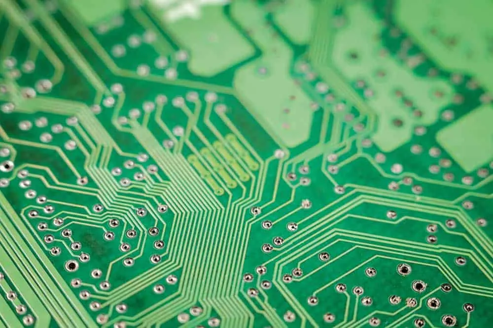
A flexible printed circuit (FPC) is a thin, bendable circuit board constructed from flexible substrate materials rather than rigid fiberglass. Unlike traditional FR-4 PCBs that maintain fixed shapes, FPCs can bend, fold, and flex during installation and operation without damaging electrical connections. This flexibility enables designs impossible with conventional rigid boards.
FPCs consist of conductive copper traces laminated between flexible insulating layers, typically polyimide or polyester films. The resulting assemblies can bend through 360 degrees and withstand millions of flex cycles in dynamic applications. Modern smartphones contain 15-20 individual flex circuits connecting displays, cameras, batteries, and antennas in spaces too tight for any other interconnection solution.
Flexible circuits emerged as engineers recognized limitations of rigid boards and wire harnesses for space-constrained and dynamic applications. By eliminating bulky connectors and reducing assembly complexity, FPCs enable smaller, lighter, more reliable products across consumer electronics, medical devices, automotive systems, and aerospace applications.
FPC Composition and Materials
Base Substrate Materials
Polyimide (PI): The predominant FPC substrate material offers exceptional thermal stability, chemical resistance, and mechanical properties. Polyimide maintains flexibility across temperature extremes from -200°C to +400°C, making it suitable for demanding applications. Common polyimide brands include Kapton and Apical.
Polyester (PET): Lower-cost alternative suitable for less demanding applications. PET substrates work well for consumer electronics where extreme temperature exposure is unlikely. Lower thermal resistance limits soldering options compared to polyimide.
Liquid Crystal Polymer (LCP): Advanced material for high-frequency applications requiring excellent dielectric properties. LCP substrates support 5G and mmWave circuits where signal integrity at high frequencies proves critical.
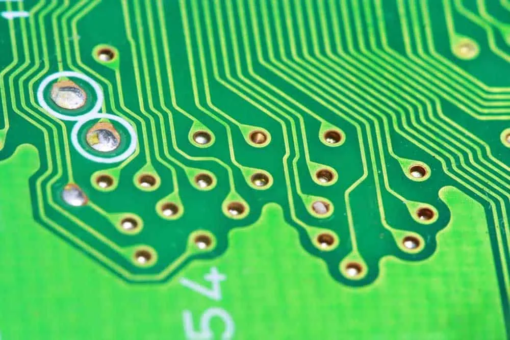
Copper Conductors
FPC copper layers typically range from 0.5oz to 2oz thickness, with thinner copper enabling tighter bend radii. Rolled annealed (RA) copper provides superior flexibility compared to electrodeposited (ED) copper, making RA copper preferred for dynamic flexing applications. Copper traces carry electrical signals while the substrate provides mechanical support and insulation.
Adhesive Layers
Traditional FPC construction uses adhesive layers bonding copper to substrate. Adhesiveless constructions eliminate this layer, directly depositing copper onto polyimide for improved thermal performance and thinner profiles. Adhesiveless FPCs better survive high-temperature soldering processes.
Coverlay
Coverlay protects exposed copper traces from oxidation, contamination, and mechanical damage. This layer typically consists of polyimide film with adhesive, applied over circuit traces while leaving component pads exposed. Coverlay serves functions similar to solder mask on rigid PCBs while maintaining flexibility.
Types of Flexible Circuits
Single-Sided FPC
Simplest construction with copper traces on one substrate side. Single-sided flex circuits suit applications with straightforward routing requirements and lower component density. Cost-effective for high-volume consumer applications.
Double-Sided FPC
Copper traces on both substrate sides connected through plated through-holes. Double-sided construction enables more complex routing and higher component density. Most common configuration for moderate complexity applications.
Multi-Layer FPC
Three or more conductive layers separated by insulating substrate, connected through plated vias. Multi-layer flex circuits support complex routing, controlled impedance, and high-density interconnections. Manufacturing capability extends to 12+ layers for demanding applications.
Rigid-Flex PCB
Hybrid construction combining rigid FR-4 sections with flexible polyimide sections in integrated assemblies. Rigid areas support component mounting and connectors while flexible sections provide dynamic interconnections. This approach eliminates separate connectors and cables between rigid boards, dramatically improving reliability. Aerospace, military, and medical applications favor rigid-flex designs for critical systems.
Sculptured Flex
Advanced construction with varying copper thickness across the circuit. Thicker copper in high-current areas, thinner copper in flex zones optimizes both electrical and mechanical performance.
Benefits of Flexible Printed Circuits
Space and Weight Reduction
Flexible circuits eliminate bulky connectors and wire harnesses, dramatically reducing assembly volume and weight. FPCs conform to available space rather than requiring space accommodation. Products become thinner, lighter, and more portable—critical advantages for mobile devices and wearables.
Dynamic Flexing Capability
Quality FPCs withstand 500 million+ flex cycles in properly designed applications. This durability enables moving components like laptop hinges, printer heads, and disk drive actuators that would quickly destroy conventional wiring. Dynamic flex applications require careful design attention to bend radius and trace orientation.
Improved Reliability
Fewer solder joints and connectors mean fewer potential failure points. Eliminating discrete wiring and connectors removes common failure modes while simplifying assembly. Reduced interconnection complexity improves manufacturing yields and field reliability.
Design Flexibility
FPCs can be cut, shaped, and formed to fit virtually any enclosure geometry. Three-dimensional routing paths impossible with rigid boards become practical. Designers gain freedom to optimize product form factors without interconnection constraints.
Thermal Management
Thin profile and direct heat paths through copper traces can improve thermal performance compared to wire harnesses. Flexible circuits spread heat effectively while fitting thermal management constraints.
Impedance Control
Consistent manufacturing processes enable precise impedance control for high-speed signals. FPCs achieve the controlled impedance required for USB, HDMI, and other high-speed interfaces while maintaining flexibility.
Simplified Assembly
Single FPC assemblies replace multiple cables, connectors, and rigid boards. Reduced part counts decrease assembly time, inventory complexity, and potential assembly errors. Automation-friendly designs improve manufacturing efficiency.
FPC Design Considerations
Bend Radius Requirements
Minimum bend radius represents the tightest curve an FPC can survive without damage. General guidelines specify minimum radius of 6x material thickness for static installations and 12x thickness for dynamic flexing applications. Thicker copper requires larger bend radii to prevent trace cracking.
Bend Zone Design
Traces crossing bend zones should orient perpendicular to the bend axis, distributing stress evenly across trace width. Avoid placing vias, pads, or plated through-holes in bend areas where stress concentration could cause failures. Stagger traces on opposite sides rather than aligning them directly over each other.
Trace Routing
Smooth curves prevent stress concentration that sharp corners would create. Gradual transitions between trace widths reduce mechanical stress. Consistent trace widths through flex zones improve reliability compared to varying widths.
Component Placement
Mount components only on rigid sections of rigid-flex designs. For all-flex circuits, use stiffeners to support component areas. Avoid placing components near bend zones where flexing could stress solder joints.
Stiffener Application
Polyimide, FR-4, or metal stiffeners reinforce areas requiring mechanical support. Stiffeners under connector areas, component mounting zones, and handling edges improve durability and assembly compatibility.
Copper Weight Selection
Lighter copper weights (0.5oz-1oz) provide better flexibility for tight bends and dynamic applications. Heavier copper (2oz+) suits high-current applications but requires larger bend radii. Balance current capacity requirements against flexibility needs.
FPC Manufacturing Process
Material Preparation
Manufacturing begins with copper-clad flexible laminate preparation. Substrate materials are cleaned, inspected, and cut to panel sizes appropriate for production equipment. Material quality directly affects finished circuit reliability.
Circuit Imaging
Photoresist applied to copper surfaces receives circuit pattern exposure through artwork films or direct laser imaging. Exposed photoresist undergoes development, revealing areas for copper removal. Imaging precision determines trace resolution capabilities.
Etching
Chemical etching removes unwanted copper, leaving designed circuit traces. Process control maintains trace width accuracy and edge quality. Over-etching reduces trace widths while under-etching leaves unwanted copper bridges.
Drilling and Plating
Mechanical or laser drilling creates via holes connecting circuit layers. Electroless copper deposition followed by electroplating establishes electrical connections through holes. Plating thickness affects via reliability and current capacity.
Coverlay Application
Polyimide coverlay with adhesive is laminated over circuits, protecting traces while exposing component pads. Registration accuracy ensures proper pad exposure. Coverlay protects against oxidation and mechanical damage during handling and operation.
Surface Finishing
Exposed copper pads receive protective finishes enabling soldering. Common options include ENIG (Electroless Nickel Immersion Gold), immersion tin, and OSP (Organic Solderability Preservative). Finish selection considers soldering requirements and storage conditions.
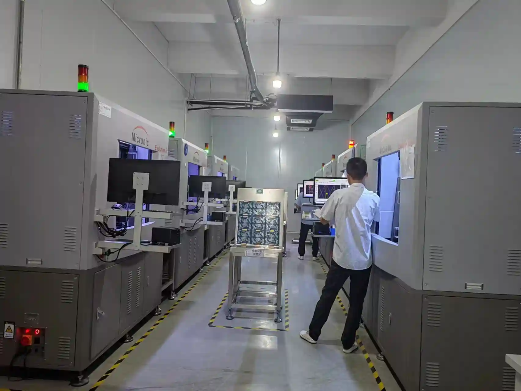
Testing and Inspection
Electrical testing verifies circuit continuity and isolation. Automated optical inspection (AOI) catches visual defects. Finished circuits undergo dimensional verification and flexibility testing appropriate for intended applications.
FPC Applications
Consumer Electronics
Smartphones, tablets, laptops, and wearables rely heavily on flexible circuits. Display connections, camera modules, battery interfaces, and antenna feeds commonly use FPCs. Foldable smartphones demonstrate extreme FPC capabilities with designs surviving hundreds of thousands of fold cycles.
Medical Devices
Implantable devices, diagnostic equipment, and patient monitors utilize FPCs for reliability in critical applications. Hearing aids, pacemakers, and neurostimulators require miniaturization only flex circuits enable. Biocompatible materials and sterilization compatibility prove essential.
Automotive Electronics
Vehicle systems increasingly incorporate FPCs for dashboard displays, sensor connections, LED lighting, and infotainment systems. Harsh temperature ranges and vibration demand robust flexible circuit designs. Weight reduction through FPC adoption supports fuel efficiency goals.
Aerospace and Defense
Weight-critical aerospace applications leverage FPCs for wire harness replacement. Satellites, aircraft systems, and defense electronics require the reliability and weight savings flexible circuits provide. Rigid-flex constructions suit avionics requiring rugged mounting with flexible interconnections.
Industrial Equipment
Robotic systems, factory automation, and industrial sensors utilize FPCs for moving component connections. Print heads, disk drives, and actuators require dynamic flex circuits surviving continuous motion.
Solar Energy
Flexible solar panel interconnections and power electronics increasingly incorporate FPCs. Thin profile and environmental resistance suit outdoor renewable energy applications.
Industry Standards
Key IPC documents govern flexible circuit design and manufacturing:
- - IPC-2223: Primary design standard for flexible printed circuits, with current revision (IPC-2223E) including guidance for HDI flex, wearables, and high-frequency applications
- IPC-6013: Performance specification for flexible printed boards covering materials, construction, and quality requirements
- IPC-A-610: Acceptability standard addressing flex circuit inspection criteria
- IPC-4202: Flexible base dielectrics specification
Summary
Flexible printed circuits enable electronic designs impossible with traditional rigid boards. Understanding materials, design principles, and manufacturing processes helps engineers leverage FPC capabilities effectively. From space-constrained consumer devices to reliability-critical medical implants, flexible circuits continue expanding into new applications as technology advances.
For custom flexible PCB manufacturing or expert design consultation, contact WellPCB for competitive quotes and engineering support.
Frequently Asked Questions
What is the difference between FPC and rigid PCB?
FPCs use flexible polyimide or polyester substrates that bend without damage, while rigid PCBs use stiff fiberglass materials maintaining fixed shapes. FPCs enable dynamic flexing and conform to enclosure geometries, but cost more than equivalent rigid boards. Choose FPC when flexibility, weight reduction, or space constraints require it.
How many times can an FPC be bent?
Properly designed dynamic flex circuits survive 500 million+ flex cycles. Static installations (bent once during assembly) tolerate tighter radii but shouldn't be repeatedly flexed. Design parameters including bend radius, copper weight, and trace orientation determine actual flex life for specific applications.
What materials are used in FPC manufacturing?
Common FPC materials include polyimide (Kapton) substrates, rolled annealed copper conductors, acrylic or epoxy adhesives, and polyimide coverlay. High-frequency applications may use LCP substrates. Material selection depends on temperature requirements, flexibility needs, and electrical performance specifications.
Are FPCs more expensive than rigid PCBs?
FPCs typically cost 2-5x more than equivalent rigid boards due to specialized materials and processing. However, total system cost may decrease when FPCs eliminate connectors, reduce assembly labor, and improve reliability. Evaluate complete assembly costs rather than bare board prices alone.
What is rigid-flex PCB?
Rigid-flex combines rigid FR-4 sections with flexible polyimide sections in integrated assemblies. Rigid areas support components and connectors while flex sections provide bendable interconnections. This hybrid approach eliminates separate cables and connectors, improving reliability for aerospace, medical, and military applications.
Related Articles
Continue exploring similar topics
AOI Testing Guide: PCB Automated Optical Inspection Explained
Complete guide to Automated Optical Inspection (AOI) for PCB manufacturing. Learn how AOI works, defect detection capabilities, 2D vs 3D systems, and implementation best practices.
Bed of Nails Test Fixture Guide: PCB In-Circuit Testing Explained
Complete guide to bed of nails test fixtures for PCB testing. Learn about fixture types, pogo pins, ICT procedures, and quality control applications.
Double-Sided PCB: Complete Design and Manufacturing Guide
Master double-sided PCB design with our comprehensive guide covering manufacturing processes, layout strategies, via specifications, and cost optimization tips.
Ready to bring your PCB design to life?
Get an instant quote for your custom PCB fabrication and assembly needs.
Get Instant Quote