FCT Testing Guide: Functional Circuit Test Methods for PCB Assembly
Complete guide to FCT (Functional Circuit Test) for PCB assembly. Learn about testing methods, fixture types, defect detection, and best practices for ensuring board functionality.
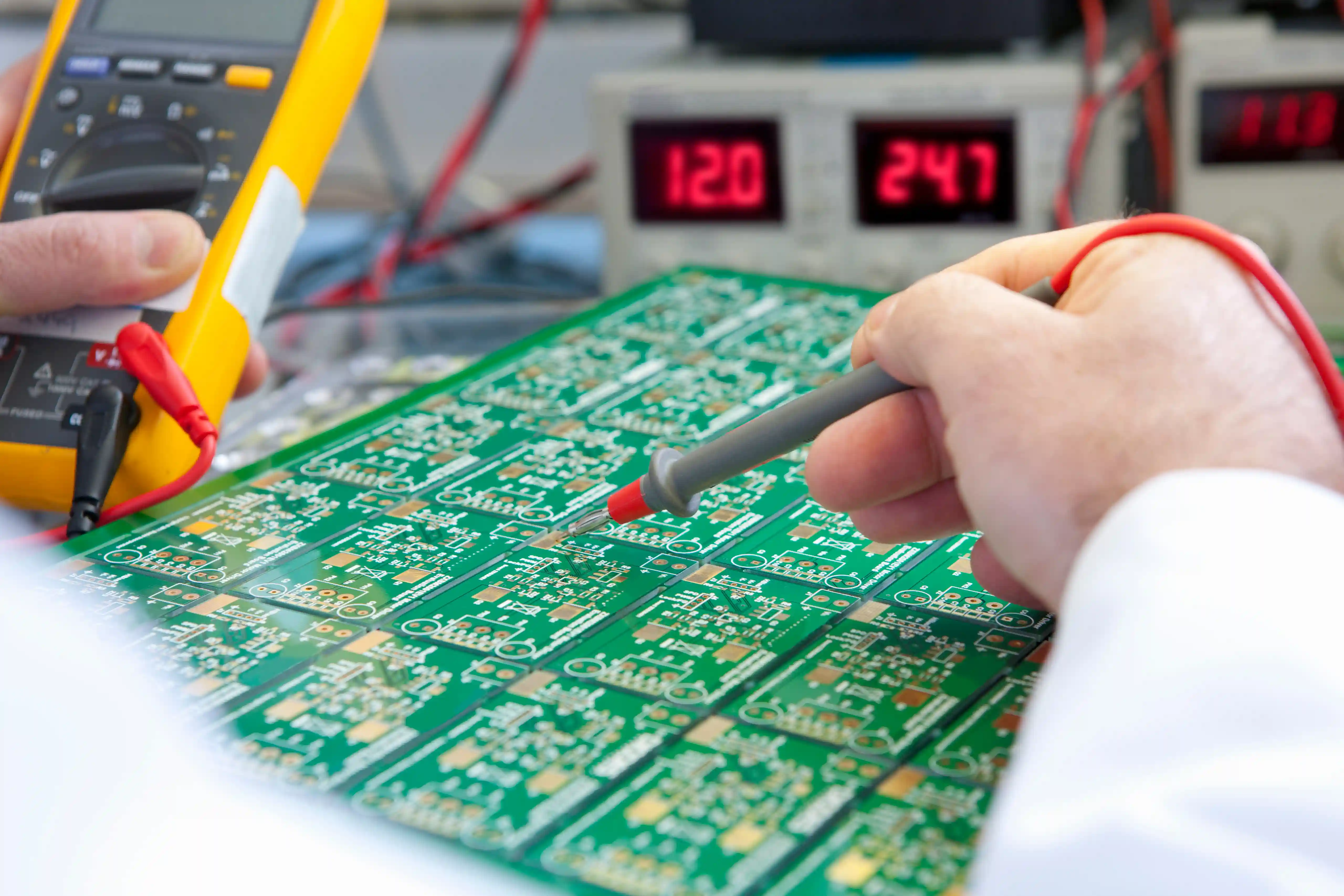
Functional Circuit Testing (FCT) validates that assembled PCBs perform their intended functions under real-world operating conditions. Unlike visual inspections or structural tests verifying physical integrity, FCT confirms boards behave correctly when powered and operating as part of complete systems. This comprehensive guide covers FCT testing methods, fixture designs, defect detection capabilities, and implementation best practices.
What is FCT Testing?
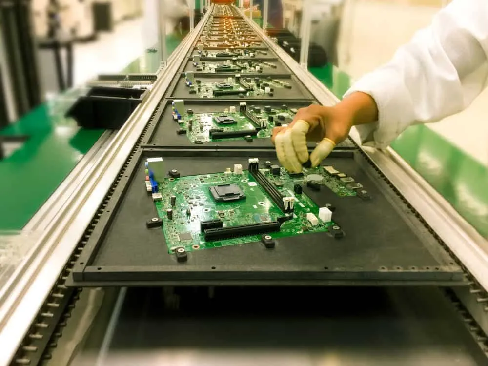
FCT stands for Functional Circuit Test, a production-stage testing method verifying assembled circuit boards operate according to design specifications. Test operators perform FCT during or after PCB assembly, typically as one of the final quality gates before boards ship to customers or integrate into finished products.
The testing process involves powering the device under test (DUT), applying input signals simulating real operating conditions, and monitoring output responses to verify correct functionality. Unlike in-circuit testing (ICT) which checks individual components, FCT evaluates the entire circuit operating as an integrated system. This holistic approach catches problems that might escape component-level testing.
FCT testing provides answers to critical questions about board functionality: Do all circuits operate within specifications when stimulated with real signals? Are power and ground networks delivering correct voltages? Do digital circuits respond correctly to logic patterns? Do analog circuits like oscillators and amplifiers perform within tolerance? Do communication interfaces transmit and receive data properly?
For electronics manufacturers, FCT serves as the final verification that boards will function correctly in customer applications. Catching functional defects before shipment prevents costly field failures, warranty returns, and damaged customer relationships.
FCT vs. Other Testing Methods
Understanding how FCT relates to other PCB testing approaches helps manufacturers implement comprehensive quality programs covering all defect types.
FCT vs. In-Circuit Testing (ICT)
In-circuit testing checks individual components and connections on assembled boards. ICT uses bed-of-nails fixtures with hundreds or thousands of probes contacting test points across the board. The test system measures component values, checks for opens and shorts, and verifies basic connectivity.
ICT excels at catching manufacturing defects—missing components, wrong values, solder bridges, open connections. However, ICT cannot verify that complete circuits function correctly together. A board might pass ICT with all components present and connected properly yet still fail functionally due to design issues, marginal timing, or subtle interaction problems.
FCT complements ICT by testing the assembled board as a complete system. Functional testing verifies circuits work correctly when operating together, catching issues ICT cannot detect. Many manufacturers use both methods—ICT for manufacturing defect screening, FCT for functional verification.
FCT vs. Flying Probe Testing
Flying probe testers use movable probes on robotic arms to contact test points sequentially rather than simultaneously. This approach eliminates custom fixture costs, making flying probe attractive for prototypes and low-volume production. However, sequential probing limits test speed compared to parallel-access bed-of-nails approaches.
Flying probe primarily performs continuity and component testing similar to ICT. While some systems can execute basic functional tests, dedicated FCT fixtures typically provide more comprehensive functional verification for high-volume production.
FCT vs. Automated Optical Inspection (AOI)
AOI uses cameras and image processing to inspect solder joints, component placement, and visible defects. This visual inspection catches assembly problems like missing components, tombstoning, solder bridges, and polarity errors.
AOI cannot detect electrical or functional defects—it only sees physical characteristics. Boards passing AOI might still have functional problems from incorrect component values, hidden solder defects, or circuit design issues. FCT provides the electrical verification AOI cannot perform.
Types of FCT Testing

Automated FCT
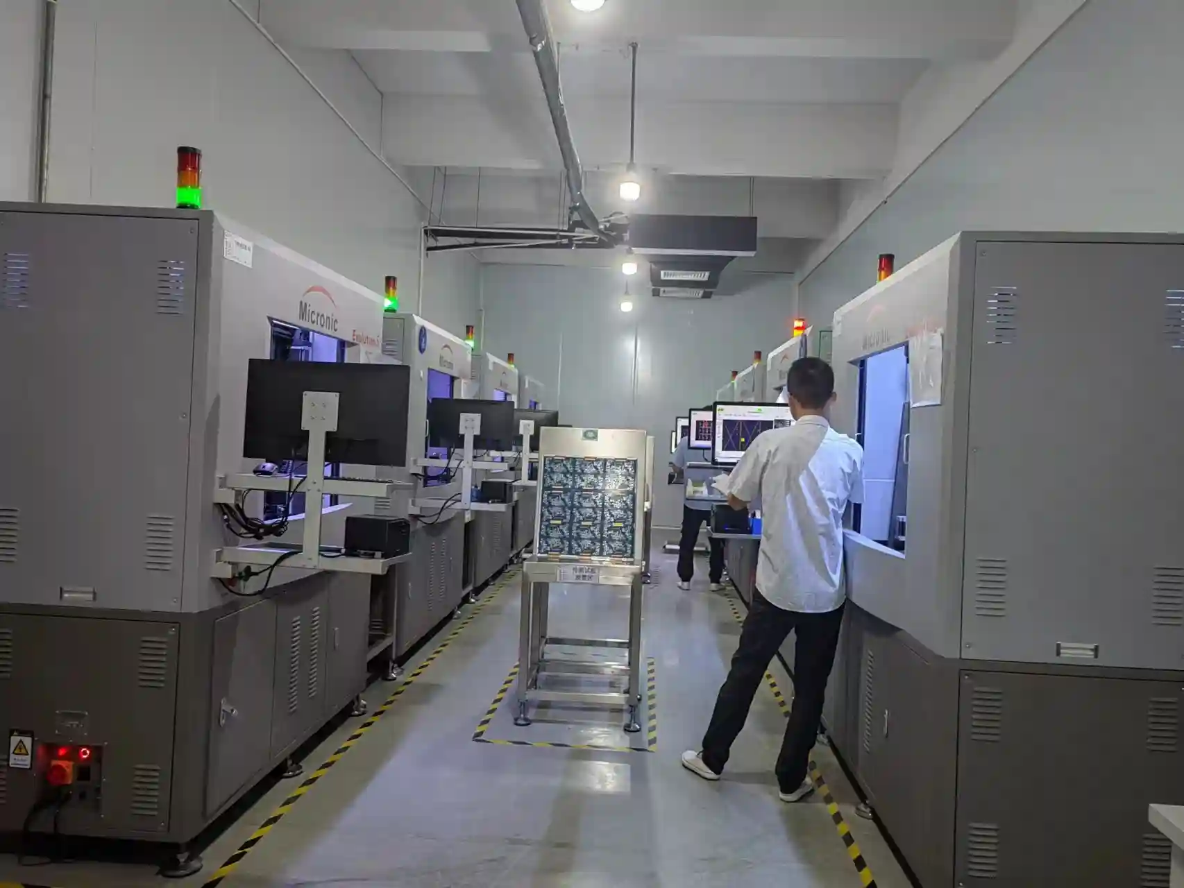
Fully automated FCT systems provide highest throughput for volume production. Boards load automatically into test fixtures, undergo programmed test sequences, and unload with pass/fail determination—all without operator intervention. Automated systems consistently execute complex test procedures while maintaining detailed data logging.
Automation suits high-volume applications where throughput and consistency matter most. Initial investment in automated systems pays back quickly when testing thousands of boards monthly.
Semi-Automated FCT
Semi-automated systems combine automatic test execution with manual board handling. Operators load boards into fixtures and initiate tests, but the test sequence runs automatically. This approach reduces fixture complexity while maintaining consistent test execution.
Semi-automated FCT suits medium-volume production where full automation isn't justified. Lower capital costs make this approach attractive for contract manufacturers handling diverse products.
Manual FCT
Manual testing involves operators using bench instruments—oscilloscopes, multimeters, signal generators—to verify board functionality. This approach provides maximum flexibility for prototypes and low-volume production but depends on operator skill and cannot match automated throughput.
Manual FCT suits engineering verification, failure analysis, and low-volume products where custom fixture development isn't economical.
Hot Mockup Testing
Hot mockup FCT tests boards within simulated system environments replicating actual operating conditions. The board connects to interfaces mimicking real system connections, allowing verification of functionality in context. This approach catches integration issues that standalone testing might miss.
FCT Fixture Design
Bed-of-Nails Fixtures
Bed-of-nails fixtures use arrays of spring-loaded pogo pins to contact test points on PCBs. Pins mount in fixture plates aligned to board test point locations. When boards press onto the fixture, pins compress to make electrical contact enabling signal injection and measurement.
Key design considerations for bed-of-nails FCT fixtures:
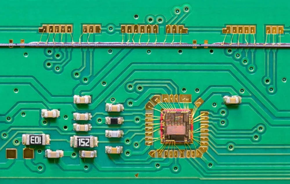
Test Point Access: Identify all signals requiring test access and ensure corresponding test points exist on the PCB layout. FCT typically requires fewer test points than ICT since functional testing focuses on system-level signals rather than every component.
Pin Selection: Choose pogo pins appropriate for signal types—standard pins for digital signals, low-inductance pins for high-frequency signals, high-current pins for power connections. Pin pitch must accommodate test point spacing on the board.
Mechanical Design: Fixtures must hold boards securely in consistent positions. Vacuum hold-down, mechanical clamps, or guide pins ensure repeatable alignment. Fixture construction must withstand thousands of test cycles without wear affecting contact reliability.
Interface Connections: Fixtures connect to test equipment through cables carrying test signals. Routing must maintain signal integrity, particularly for high-speed or sensitive measurements.
Flying Probe Hybrid Fixtures
Some FCT applications combine fixed bed-of-nails contacts for primary signals with flying probes accessing secondary test points. This hybrid approach balances fixture cost against test coverage, using fixed contacts where speed matters and probes where occasional access suffices.
Production Considerations
FCT fixtures represent significant investments—design time, fabrication cost, and validation effort. Fixture complexity scales with test requirements, ranging from simple manual fixtures costing hundreds of dollars to automated fixtures costing tens of thousands. Design decisions should balance test coverage needs against fixture cost and production volume.
Defects Detected by FCT
Functional Failures
Circuit Logic Faults: Circuits failing to respond correctly to input stimuli due to component problems, connection issues, or design flaws. FCT applies test patterns and verifies expected outputs.
Timing Issues: Marginal timing relationships between signals causing intermittent failures. FCT can detect setup/hold violations and race conditions that might not appear during slower ICT testing.
Analog Performance: Amplifiers, oscillators, filters, and other analog circuits operating outside specification limits. FCT measures parameters like gain, frequency response, and distortion against design requirements.
Power Integrity Issues
Voltage Problems: Incorrect supply voltages from missing components, wrong values, or regulator failures. FCT monitors power rails under load, catching issues that static testing might miss.
Power Sequencing: Improper startup sequences that could damage components or prevent correct initialization. FCT can verify sequencing timing meets requirements.
Noise and Ripple: Excessive power supply noise affecting circuit performance. FCT measures ripple under realistic load conditions.
Signal Integrity Issues
Signal Distortion: Excessive ringing, overshoot, or undershoot degrading signal quality. FCT with oscilloscope measurements can characterize signal integrity.
Crosstalk: Unintended coupling between adjacent signals causing interference. FCT can detect crosstalk effects on functional behavior.
Impedance Faults: Transmission line impedance variations affecting high-speed signal integrity. FCT may reveal problems that appear only at operating speeds.
Intermittent Defects
Marginal Connections: Solder joints or component connections that work sometimes but fail under stress. FCT under varying conditions can expose marginal connections.
Temperature Sensitivity: Defects appearing only at temperature extremes. FCT with thermal stress can identify temperature-sensitive failures.
FCT Test Development Process
Test Specification
Effective FCT begins with clear test specifications defining:
- - Functions requiring verification
- Input stimuli for each test
- Expected outputs and tolerance limits
- Pass/fail criteria for each measurement
- Test sequence and timing requirements
Specifications should derive from design requirements, ensuring tests verify intended functionality rather than arbitrary parameters.
Test Program Development
Test programs implement specifications in executable form. Modern FCT systems use graphical programming environments or scripting languages to define test sequences. Programs specify:
- - Stimulus generation parameters
- Measurement configurations
- Comparison limits and pass/fail logic
- Data logging and reporting formats
- Error handling procedures
Program development requires collaboration between test engineers understanding equipment capabilities and design engineers understanding circuit behavior.
Fixture Design and Fabrication
Fixture design translates test requirements into mechanical implementations. Design activities include:
- - Test point mapping from PCB layout data
- Pogo pin selection and placement
- Mechanical structure design
- Wiring and cable routing
- Interface connector specification
Fabrication involves precision machining of fixture plates, pin installation, and wiring. Fixture validation verifies correct contact with all test points.
Test Validation
Before production deployment, test programs and fixtures require validation:
- - Verify correct test point contact using known-good boards
- Confirm measurement accuracy against reference standards
- Test fault coverage using boards with known defects
- Verify pass/fail discrimination catches defective boards
- Validate repeatability with multiple test cycles
Best Practices for FCT Implementation
Design for Testability
Effective FCT requires boards designed with testing in mind:
Test Point Placement: Include accessible test points for critical signals. Locate points on board edges or areas clear of tall components allowing fixture access.
Built-In Test Features: Consider incorporating test modes, loopback paths, or BIST (Built-In Self-Test) capabilities that simplify functional verification.
Documentation: Maintain clear documentation of test point functions and expected signal characteristics for test development reference.
Statistical Process Control
FCT generates valuable data for process monitoring:
Yield Tracking: Monitor pass/fail rates over time to identify process trends and anomalies requiring investigation.
Parameter Trending: Track measurement values even for passing boards. Drifting parameters may indicate developing problems before failures occur.
Failure Analysis: Investigate all failures to identify root causes. Pattern recognition across multiple failures often reveals systematic issues.
Continuous Improvement
FCT programs should evolve continuously:
Coverage Expansion: Add tests addressing field failures or newly identified risks.
Efficiency Optimization: Reduce test time through parallel measurements, optimized sequences, or improved fixtures.
Fault Coverage Analysis: Periodically assess whether tests catch known defect types and add coverage for gaps.
FCT Testing Economics
Cost Considerations
FCT implementation involves several cost categories:
Fixture Costs: Custom fixtures range from hundreds to tens of thousands of dollars depending on complexity. Amortize costs over expected production volume.
Equipment Costs: Test systems range from bench instruments for manual testing to automated stations costing $50,000-$500,000+. Equipment selection should match throughput requirements.
Development Costs: Test program and fixture development requires engineering time. Complex products may require weeks of development effort.
Operating Costs: Labor for test operation, maintenance, and troubleshooting. Automated systems reduce but don't eliminate operating costs.
Return on Investment
FCT delivers returns through defect prevention:
Avoided Field Failures: Each defect caught before shipment prevents costly field failure investigation, repair, and customer dissatisfaction.
Reduced Rework: Catching defects at FCT costs less than finding them later in system integration or customer use.
Process Feedback: FCT data identifies manufacturing problems, enabling corrections that improve yield and reduce overall costs.
The ROI calculation compares FCT costs against defect risks. Even modest defect rates (1-2%) often justify thorough FCT programs, particularly for complex or safety-critical products.
Summary
Functional Circuit Testing validates that assembled PCBs perform intended functions correctly before deployment. By testing boards under realistic operating conditions, FCT catches defects that other testing methods miss—functional failures, timing issues, power integrity problems, and intermittent defects. Effective FCT implementation requires appropriate fixture design, thorough test development, and continuous improvement based on test data. While FCT represents significant investment, the return through defect prevention typically justifies comprehensive testing programs.
For PCB assembly with comprehensive FCT and quality testing services, contact WellPCB for reliable production and testing solutions.
Frequently Asked Questions
What is the difference between FCT and ICT testing?
ICT (In-Circuit Testing) checks individual components and connections, detecting manufacturing defects like missing parts or solder problems. FCT (Functional Circuit Testing) verifies the complete assembled board operates correctly as an integrated system. ICT catches manufacturing defects; FCT catches functional problems. Many manufacturers use both methods for comprehensive coverage.
When should FCT testing be performed?
FCT typically occurs after assembly completion, serving as a final quality gate before boards ship. Some manufacturers perform FCT after ICT or AOI, using earlier tests to catch obvious defects before functional verification. FCT should occur after all assembly operations complete but before conformal coating or potting that might interfere with test access.
How much does FCT testing cost per board?
FCT cost per board varies widely depending on test complexity, fixture type, and production volume. Simple manual tests might cost $5-20 per board. Automated FCT for volume production might cost $0.50-5 per board including fixture amortization. Complex tests with extensive measurements cost more than simple pass/fail checks.
What defects can FCT detect that ICT cannot?
FCT detects functional problems invisible to ICT: timing failures, analog performance issues, power sequencing problems, software-related defects, and system-level integration issues. ICT verifies components are present and connected; FCT verifies the complete circuit works correctly.
How long does FCT test development take?
Test development time depends on product complexity. Simple boards with straightforward functionality might require days of development. Complex products with extensive testing requirements might need weeks or months. Development includes test specification, program creation, fixture design, fabrication, and validation.
Related Articles
Continue exploring similar topics
AOI Testing Guide: PCB Automated Optical Inspection Explained
Complete guide to Automated Optical Inspection (AOI) for PCB manufacturing. Learn how AOI works, defect detection capabilities, 2D vs 3D systems, and implementation best practices.
Bed of Nails Test Fixture Guide: PCB In-Circuit Testing Explained
Complete guide to bed of nails test fixtures for PCB testing. Learn about fixture types, pogo pins, ICT procedures, and quality control applications.
Double-Sided PCB: Complete Design and Manufacturing Guide
Master double-sided PCB design with our comprehensive guide covering manufacturing processes, layout strategies, via specifications, and cost optimization tips.
Ready to bring your PCB design to life?
Get an instant quote for your custom PCB fabrication and assembly needs.
Get Instant Quote