Custom Molded Cable Manufacturing
Overmolded Cable Assembly for Durable OEM Interconnects
PCB Insider builds overmolded cable assemblies when a connector, split, or cable exit needs controlled strain relief, cleaner installation, and test evidence before it reaches your product line.
100%
Electrical Test Planning
IPC/WHMA-A-620
Workmanship Reference
Prototype to Production
Program Stage
Cable + Box Build
Integration Scope
TL;DR
- Overmolded cable assembly protects connector exits, splits, and cable-to-product transitions from handling and pull stress.
- Best-fit projects need repeatable strain relief, clean installation, sealing, or a molded appearance.
- Send drawings, pinout, connector MPNs, cable OD, mold shape, material notes, test rules, and quantity.
- We support cable assembly, PCB assembly, enclosure routing, and box build when the cable is part of a larger product.
Molded Cable Decisions Should Be Made Before Tooling
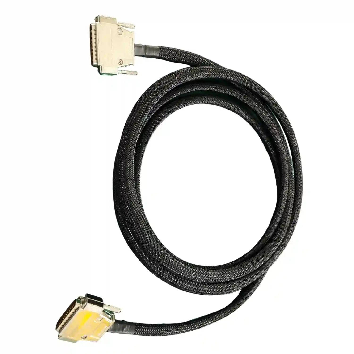
Overmolded cable assembly is a manufacturing service that forms a molded compound around a cable termination, connector, branch, or exit point. A cable assembly is an electrical interconnect built from wires, cables, connectors, labels, and protection features. When the cable becomes part of a product the buyer touches, installs, or services, the molded geometry can matter as much as the pinout.
Strain relief is a mechanical feature that spreads bending and pulling loads away from fragile terminations. We use IPC electronics workmanship context, IPC/WHMA-A-620 cable acceptance expectations, and product-specific drawings to decide whether a molded boot, heat-shrink support, adhesive-lined sleeve, or enclosure-side grommet is the right answer.
Molded Connector Exits
Overmolded cable assembly protects connector exits, solder cups, crimped contacts, and jacket transitions where repeated handling would otherwise create early failures.
Strain Relief and Bend Control
We review boot geometry, cable diameter, minimum bend radius, pull direction, and installation path before the mold is released.
Tooling and Sample Validation
Prototype molds, first samples, customer fit checks, and production tooling decisions are separated so buyers can control cost before volume release.
Material and Connector Sourcing
PVC, TPU, TPE, shielded cable, RF coax, braided cable, and specified connector families are quoted with source visibility and substitution control.
Test Evidence Before Shipment
Continuity, hipot where specified, pinout, visual inspection, pull checks, and labeling records are aligned to the drawing and acceptance notes.
Integration With Electronics Builds
The same supplier path can support molded cables, PCB assemblies, enclosure routing, labels, and final packing when a program needs fewer handoffs.
Capability Scope and RFQ Inputs
Service focus
Custom overmolded cable assembly for OEM power, signal, RF, sensor, industrial, and electronics programs
Cable formats
Discrete wire cable, shielded control cable, braided cable, micro-coax, RF coax, Ethernet, hybrid power-signal cable
Molded areas
Connector backshells, Y-splits, strain-relief boots, grommets, panel exits, enclosure pass-throughs, and cable-to-board transitions
Material options
PVC, TPU, TPE, silicone by review, low-smoke cable jackets, braided sleeving, heat-shrink, and customer-specified compounds
Connector scope
Circular connectors, sealed automotive connectors, D-sub, RJ45, RF connectors, board-to-wire connectors, and specified OEM connectors
Quality controls
Pinout test, continuity, hipot by drawing, pull checks, visual criteria, sample approval, and serialized packing when required
Required files
Cable drawing, connector part numbers, pinout, cable OD, material notes, color requirements, marking notes, annual quantity, and target environment
Best fit
Programs where strain relief, sealing, handling durability, or installation appearance matters more than a loose crimped cable set
UL 758 is a safety-related appliance wiring material standard often referenced when cable materials and markings need tighter control. The public UL overview gives background on the organization behind many recognized material programs, while the final material approval path should be confirmed against your product requirement.
Hommer Zhao on Molded Cable Risk
"For molded cable work, I want the drawing, cable OD, mold reference, and test method in the same review. If those are separated, the sample can look correct but fail the customer's installation or test fixture."
Manufacturing Process for Overmolded Cables
The process is built around sample approval because tooling, compound behavior, cable jacket tolerance, and connector retention interact. For outdoor or enclosure-exit products, ingress protection rating targets can also affect boot geometry, gasket choice, and whether the cable entry should be solved at the connector or enclosure level.
Step 1
Review the cable use case
We start with the cable drawing, mating connector, pinout, bend direction, operating environment, pull risk, label rules, and expected order volume.
Step 2
Lock connector, cable, and material choices
The engineering review checks cable OD tolerance, jacket compatibility, shield termination, insert molding limits, and whether any substitute connector needs buyer approval.
Step 3
Build and inspect first samples
Sample pieces are checked for fit, pinout, visual molding defects, strain-relief geometry, marking clarity, and any assembly issue that should be corrected before production tooling.
Step 4
Release controlled production
Approved builds move through cutting, stripping, termination, molding, curing or cooling, electrical test, visual inspection, labeling, and packing against the agreed record set.
Overmolding Compared With Other Cable Protection Choices
The correct protection method depends on production quantity, pull force, environment, service access, tooling budget, and how visible the cable is in the finished product.
Heat-shrink boot
Low tooling cost and fast samples
Good for prototypes or internal wiring, but weaker for shape control and sealed external exits.
Overmolded cable
Controlled shape, bend relief, retention, and appearance
Best when the cable is handled by users, routed through equipment, or exposed to vibration and abrasion.
Potted cable exit
Encapsulation around a cavity or enclosure exit
Useful for moisture or tamper resistance, but harder to service and less flexible for connector-end ergonomics.
A low-MOQ pilot may start with heat-shrink while the team confirms cable routing. Once the shape, pull direction, and connector exit are stable, overmolding gives a repeatable production part with better appearance and fewer assembly variables.
What To Send Before We Quote Tooling
A useful overmolded cable quote needs enough data to separate cable cost, connector cost, mold complexity, test method, and tooling risk. Send drawings, photos of the target installation, connector MPNs, cable construction, pinout, annual quantity, sample quantity, and any pull, bend, color, or marking criteria.
If the cable connects to a PCB assembly or enclosure, include that context early. Our box build assembly and PCB assembly teams can review orientation, clearance, test access, and packing as one release package.
Overmolded Cable Assembly FAQ
Answers for procurement and engineering teams comparing molded cable suppliers before releasing tooling or sample POs.
What is an overmolded cable assembly?
An overmolded cable assembly is a cable set with molded material formed around a connector, split, exit, or strain-relief area. The goal is to protect terminations, control bend shape, improve handling durability, and create a cleaner installed product than loose boots or heat-shrink alone.
What files do you need for an accurate quote?
Send the cable drawing, connector manufacturer part numbers, pinout, cable OD, jacket and compound requirements, overmold shape or reference photo, color and marking notes, test requirements, annual quantity, and target lead time. If the mold shape is not frozen, a rough sketch is enough for an engineering review before tooling cost is locked.
When should we choose overmolding instead of heat-shrink strain relief?
Choose overmolding when the cable will be handled often, pulled during installation, exposed to abrasion, routed outside an enclosure, or judged by finished-product appearance. Heat-shrink is faster and cheaper for low-risk internal wiring. Overmolding is usually better when repeatable bend control, retention, and sealed connector exits are part of the acceptance criteria.
Can you support specialized braided or marked cable requirements?
Yes. In one mining-sector project, the buyer required 3 Core (Yellow, Red, Blue), 18 AWG GXL, Black braid with 2 blue stripes, 50m or 100m rolls plus laser-etched markings and injection-molded connectors. That type of detail belongs in the RFQ because cable construction, marking, and molding must be validated together.
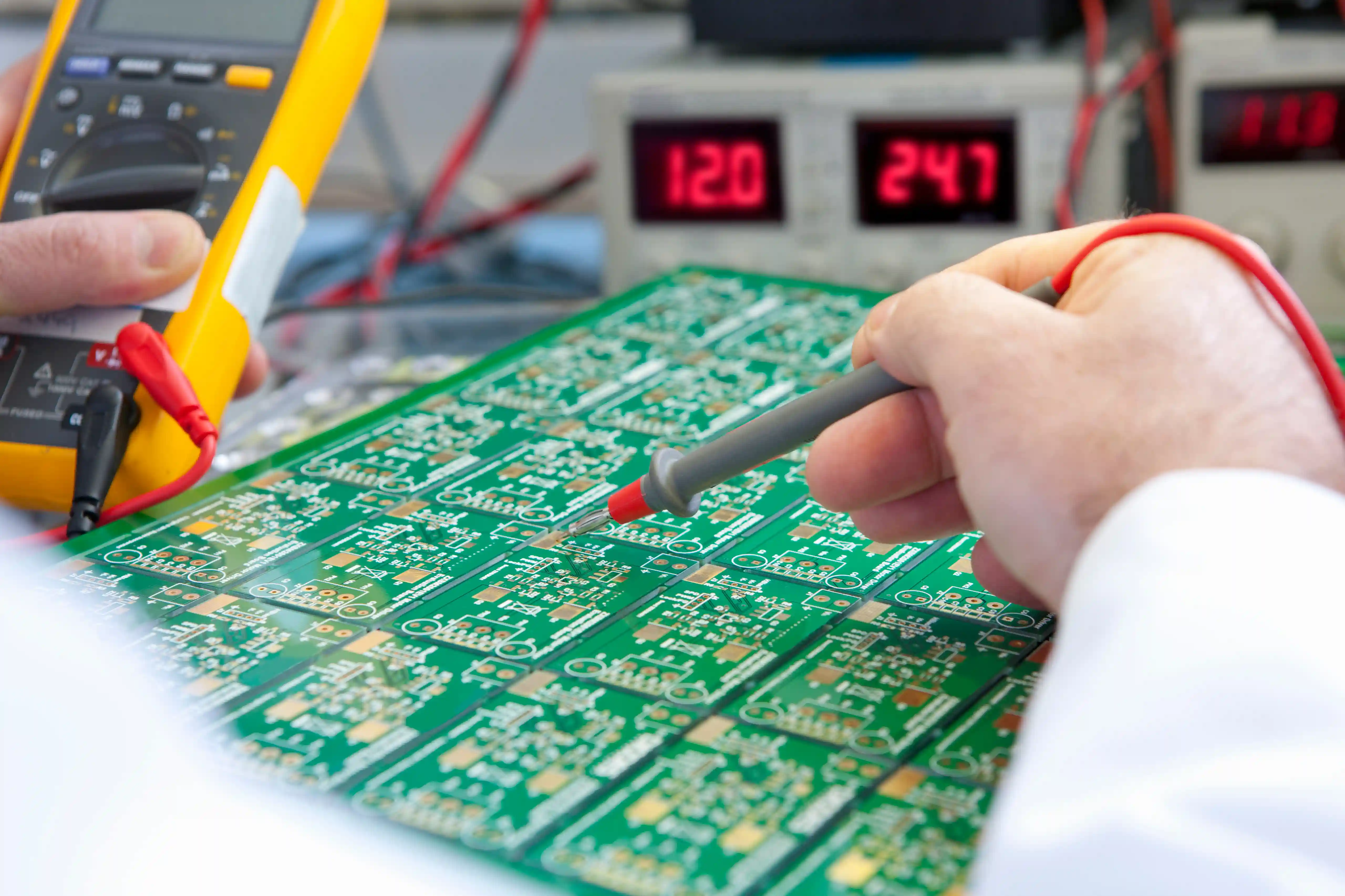
Do overmolded cable assemblies need electrical testing?
Yes. Molding can hide terminations, so electrical test should not be treated as optional. We plan continuity, pinout, hipot where specified, and visual inspection after molding. For high-risk signal cables, we also review whether impedance, shielding, or test-method alignment is needed before volume production.
Can you combine molded cables with PCB assembly or box build?
Yes. Many programs use molded external cables with PCBAs, internal harnesses, enclosure cable entries, and final functional test. If the molded cable plugs into a board or routes through an enclosure, share the PCBA and box-build context early so connector orientation, strain relief, and packing are not solved separately.
A representative imaging case (illustrative) shows why test-method alignment must be settled before volume. The fine-gauge micro-coax program saw a large share of a lot fail, then a full replacement build after the team stopped production, aligned the specification and test method, and rebuilt the affected quantity.
Related Services
Overmolded cable programs often touch standard cable assembly, recognized-material builds, RF cables, and enclosure integration.
Custom Cable Assembly
Use this page when the cable construction, connector set, and pinout are the main sourcing scope.
View serviceUL CSA Certified Cable Assembly
Use this page when recognized materials, label control, and compliance documentation are central to the RFQ.
View serviceRF Cable Assemblies
Use this page when coax routing, impedance, connector fit, and RF test expectations define the cable risk.
View serviceBox Build Assembly
Use this page when molded cable exits must be integrated with enclosures, PCBAs, and final system test.
View serviceNeed a Molded Cable Quote With Tooling Risk Visible?
Send the drawing, connector list, cable construction, mold notes, test requirements, and target quantity. We will review the cable, tooling, and integration path before quoting production.
Start RFQ Review