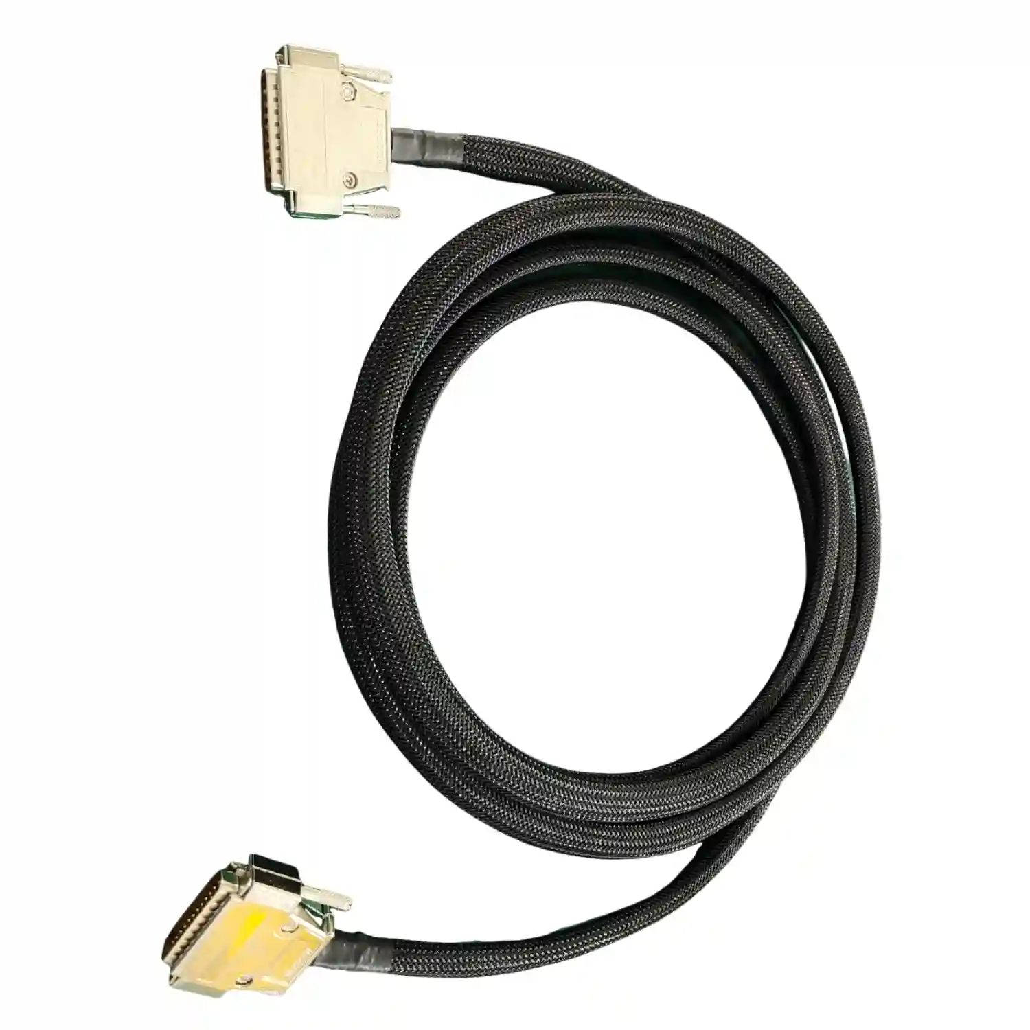
Fine-gauge RF, LVDS, camera, and sensor cable builds
Micro-Coax Cable Assembly for Compact RF and Imaging Devices
PCB Insider builds micro-coax assemblies where the real risk is not the cable name on the BOM, but connector fit, fine-gauge handling, bend state, and the exact impedance test method approved before production.
Fine Gauge
Micro-coax handling focus
I-PEX / U.FL
Miniature connector review
100%
Continuity test by released plan
IPC-A-620
Cable workmanship reference
TL;DR
- Micro-coax cable assembly fits compact RF, LVDS, camera, imaging, and sensor products where shielding and small bend radius matter.
- PCB Insider reviews connector fit, strip length, bend state, impedance method, and sample validation before repeat production.
- This service is narrower than general RF cable assembly: it focuses on fine-gauge miniature coax and board-level connectors.
- Quote review needs drawings, connector series, cable family, length, pinout, test limits, target quantity, and approved alternates.
Capability Boundary
Fine-gauge coax is a process-control problem before it is a purchasing problem
A micro-coax cable assembly is a miniature shielded interconnect used to carry RF, LVDS, imaging, camera, or sensor signals through compact products. It gives the design team shielding and routing flexibility, but it also removes process margin: a damaged center conductor, overworked shield, tight bend, or poorly seated I-PEX style connector can change the measurement enough to stop a lot.
PCB Insider positions this page separately from our broader RF cable assemblies service. RF cable assembly covers larger coax families and system interconnects; micro-coax cable assembly focuses on miniature board-level connectors, short routed lengths, fine-gauge handling, and buyer-approved impedance or continuity evidence.
For neutral technical background, a coaxial cable uses concentric conductor geometry to preserve a controlled signal path. I-PEX micro-coaxial connector guidance notes that these harnesses can support high-speed interfaces such as USB 3.1, Thunderbolt 3, eDP HBR3, and PCIe Gen 3/4 when the connector and cable system are selected correctly.
Fine-Gauge Micro-Coax Builds
Micro-coax cable assembly covers miniature shielded signal paths where conductor damage, shield prep, and connector handling can change electrical behavior. We review cable family, length, pinout, strip window, bend state, and handling limits before production release.
I-PEX, U.FL, and Board-Level Connector Review
Miniature connectors are checked as a system: mating height, latch style, pull direction, solder tail or crimp interface, board clearance, and approved alternatives. That reduces the risk of a sample passing mechanically while the production lot fails at receiving inspection.
Impedance and Test-Method Alignment
Impedance-related rejects often come from a mismatch between drawing limits, fixture contact, cable bend state, and the customer's measurement method. We lock the test method before sample approval so production evidence matches the buyer's acceptance rule.
Connector Prep and Microscopic Inspection
Fine coax termination needs controlled stripping, shield treatment, dielectric exposure, solder or crimp control, and magnified inspection. The goal is to protect the center conductor and ground return path without creating stiffness at the connector exit.
Alternative Connector Validation
When original I-PEX, Hirose, JAE, or U.FL-family parts are constrained, we can build validation samples with approved alternatives and separate the commercial shortage problem from the engineering acceptance decision.
Release Evidence for OEM Buyers
Production lots can include drawing revision, cable lot, connector lot, operator date, continuity result, impedance-related result by agreed method, visual inspection notes, and deviation approval when alternates are used.
Real Project Snapshot
I-PEX connector alternative validation for a thermal-imaging OEM
A European sensing equipment manufacturer faced a shortage on a critical IPEX connector used in a micro-coax assembly. The customer said it was impossible to receive cables with the correct connectors, so the build could not continue under the original material plan.
PCB Insider sourced an alternative connector, built validation samples, and submitted the assemblies for customer functional testing instead of changing the production BOM quietly.
Concrete numbers from the case bank
fine-gauge wire, 10 sample units, IPEX connector alternative
The samples passed the customer's testing with approval, allowing production to continue without guessing at connector equivalence.
Technical Scope and Limits
Micro-coax quoting moves fastest when the RF, mechanical, and test expectations are written into the same release package.
| Service focus | Custom micro-coax cable assembly for compact RF, imaging, LVDS, camera, sensor, and board-level signal links |
| Connector families | I-PEX / MHF style, U.FL, Hirose, JAE, MMCX, MCX, board-side transitions, and customer-defined miniature interfaces by review |
| Cable types | Fine-gauge micro-coax, miniature coax, shielded signal cable, hybrid micro-coax plus discrete wire by drawing review |
| Typical checks | Continuity, shorts, pinout, visual inspection, mating fit, dimensional check, and impedance-related screening when specified |
| Input files | Drawing, pinout, connector series, cable family, length, bend or routing limits, target impedance, test method, quantity, and approved alternates |
| Quality references | IPC/WHMA-A-620 cable workmanship, ISO 9001:2015 document control, and customer drawings for electrical acceptance limits |
| Best-fit programs | Thermal imaging, medical probes, compact cameras, robotics sensors, display links, embedded RF modules, and NPI lots with constrained connectors |
| Out of scope | Antenna tuning, RF certification, unreleased product debugging, and impedance guarantees without a buyer-approved test method and fixture condition |
IPC/WHMA-A-620 is a workmanship reference for cable and wire harness assemblies, while ISO 9001:2015 controls document discipline and corrective action. For public background on the electronics standards organization, see IPC electronics; for connector-specific design context, use the I-PEX micro-coaxial and twinaxial connector overview linked above.
When micro-coax is the right cable family
Micro-coax is the right choice when the design needs shielding and signal integrity in less space than a standard RF cable can comfortably occupy. It is not the default answer for every internal lead; a flat cable, discrete harness, or larger coax can be better when the electrical risk is lower or the mechanical envelope allows more room.
"For miniature coax, the first article is not only a sample. It is a test-method agreement. If the buyer and supplier measure the cable differently, production will fail even when operators built what the drawing seemed to request."
Hommer Zhao
Founder & Technical Expert, PCB Insider
| Option | Typical fit | Decision rule |
|---|---|---|
| General RF cable assembly | SMA, BNC, FAKRA, TNC, and larger coax | Use for cabinet, antenna, telecom, and test-equipment links with larger connector systems. |
| Micro-coax cable assembly | I-PEX, U.FL, board camera, LVDS, sensor, and imaging links | Use when the risk is fine-gauge handling, board clearance, bend radius, and small connector validation. |
| FFC or FPC cable assembly | Flat flexible cable or printed flex tails | Use when pitch, routing flatness, and connector insertion matter more than coaxial shielding. |
| Discrete wire harness | Power, low-speed signal, switches, and sensors | Use when current rating, crimp pull force, and branch routing dominate the design. |
| Hybrid cable set | Micro-coax plus power, ground, or control wires | Use when the device needs shielded signal paths and conventional wiring in one routed assembly. |
Production Release Process
The process is built to stop connector substitution, impedance ambiguity, and sample-to-production drift before they become shipment disputes.
1
Review the signal path and connector stack
Engineering checks cable family, connector series, pinout, mating height, route length, bend limit, board clearance, and target impedance before quoting the assembly.
2
Lock alternates and acceptance limits
If the original connector is constrained, proposed alternatives are separated from released parts, and the buyer approves sample criteria before production purchasing begins.
3
Build first samples under controlled handling
Operators prepare the fine coax with released strip lengths, shield treatment, connector instructions, and inspection points so the sample represents the production method.
4
Validate fit and electrical behavior
Samples are checked for continuity, pinout, mating fit, visual condition, and impedance-related behavior when the drawing defines the test method and fixture condition.
5
Release the production traveler
Approved instructions lock cable lot, connector lot, strip settings, inspection rules, test evidence, labels, packaging, and any deviation notes for repeat orders.
Applications
Micro-coax assemblies are strongest when a compact product must preserve signal behavior through a tight mechanical route. PCB Insider can also coordinate the cable with PCB assembly and box build assembly when the cable is installed inside the final product.
- Thermal imaging modules and compact sensing equipment
- Camera links, vision sensors, drones, and robotics end-effectors
- Medical probes, diagnostic accessories, and low-noise instrument leads
- LVDS, eDP, display, and board-to-board signal jumpers
- Embedded RF modules, GNSS antennas, and compact IoT devices
- Box-build products that combine PCB assembly, micro-coax, and internal wiring
Case-bank recovery note
A European thermal imaging OEM halted a beta production series after high impedance defects on a fine-gauge micro-coax assembly. The case-bank record lists the concrete numbers as: fine-gauge wire, fine micro-coax 1:1, 100mm length, a portion of units found nonconforming units out of recently, 1296 replacement units.
The recovery path was not a faster remake alone. Production stopped, the customer engineering team joined the root-cause review, the specification and testing method were updated, new samples and reports were issued, and the replacement order moved only after the acceptance method was clear.
Review the impedance release gateFAQ: Micro-Coax Cable Assembly
What is a micro-coax cable assembly?
A micro-coax cable assembly is a miniature shielded signal cable with a center conductor, dielectric, shield, jacket, and compact connector such as I-PEX MHF or U.FL. It is used when a product needs RF, LVDS, camera, imaging, or sensor signals in very tight space. The important controls are not only length and pinout; fine-gauge stripping, shield continuity, bend radius, connector seating, and the agreed impedance test method all affect whether the finished assembly passes.
I need 10 micro-coax samples with an alternate I-PEX connector. Can you validate that before production?
Yes. PCB Insider can build validation samples before a production lot when an I-PEX connector alternative is required. One case-bank example involved a European sensing equipment manufacturer where original IPEX connectors were unavailable; the factory sourced an alternative, manufactured 10 sample units, and submitted them for customer functional testing. The production decision should stay gated until the buyer approves mechanical fit, electrical behavior, and the alternate part number in the drawing or deviation record.
What files are needed to quote micro-coax cable assembly?
A useful quote package includes the assembly drawing, pinout, connector series, cable family, length, tolerance, bend or routing limits, target impedance, test method, target quantity, packaging needs, and approved alternates. Photos of the installed condition help when the cable exits a tight enclosure or mates with a board-mounted connector. If the RF or imaging path has a fixture-specific impedance rule, include the fixture condition and pass/fail limits before samples are built.
How do you prevent high impedance failures in fine-gauge micro-coax lots?
High impedance failures are prevented by locking the cable construction, strip length, connector prep, bend state, mating fixture, and measurement method before volume release. A case-bank recovery project recorded fine micro-coax 1:1, 100mm length, a portion of units found nonconforming units out of recently, 1296 replacement units. The lesson is direct: production should stop when the test method and drawing definition disagree, then restart only after new samples and reports pass the approved method.
Should I choose micro-coax, FFC, or a standard RF cable for a compact device?
Choose micro-coax when the design needs shielding, high-speed signal integrity, compact routing, and miniature board connectors. Choose FFC when a flat cable, repeated insertion, or low-profile display route is the main requirement. Choose a standard RF cable when SMA, BNC, FAKRA, MMCX, or other larger RF connectors fit the mechanical envelope. For camera, thermal imaging, LVDS, and embedded RF links, PCB Insider reviews the signal path and route constraints before recommending the cable family.
What standards matter for micro-coax cable workmanship and release evidence?
IPC/WHMA-A-620 matters because it defines widely used workmanship expectations for cable and wire harness assemblies, while ISO 9001:2015 matters for document control, traceability, and corrective action discipline. For neutral background, IPC is an electronics standards organization, and ISO 9000 describes the quality-management family behind ISO 9001. The final acceptance rule still comes from the buyer drawing: connector series, pinout, electrical limits, fixture condition, and revision control.
Can micro-coax cable assembly continue into PCB assembly or box build?
Yes. Micro-coax cable assembly can be handled as one part of a larger electronics manufacturing program when the product also needs PCB assembly, programming, functional test, enclosure routing, labels, and final packing. This is useful for compact imaging modules, sensor boxes, and RF-enabled instruments where the cable path and board connector cannot be validated separately. The traveler should define whether micro-coax test happens before PCBA integration, after box build, or at both gates.
Related Services
RF Cable Assemblies
Use this broader RF path when the design uses SMA, BNC, FAKRA, MMCX, or multi-GHz coaxial interconnects beyond miniature board cables.
Custom Cable Assembly
Use this path for mixed conductor cable sets, strain relief, labeling, and production documentation beyond the micro-coax signal link.
FFC Cable Assembly
Compare FFC and micro-coax when the design decision is between flat flexible routing and shielded miniature signal paths.
Coaxial Pogo Pin Connectors
Useful for RF docking, fixture, or blind-mate interfaces where compression contact matters more than a routed cable lead.
Engineering Reading
Micro-Coax Cable Impedance Testing
Use this buyer guide to define impedance method, replacement-lot evidence, and release gates for fine-gauge coax programs.
Phase Stability in RF Cable Assemblies
Helpful when flexing, temperature, or connector geometry can shift electrical length in the finished cable.
Coaxial Connector Types
Compare connector families before choosing a miniature coax or larger RF interface for the next revision.
Need micro-coax samples before a production release?
Send the drawing, connector series, cable family, pinout, target impedance, quantity, and any approved alternatives. We will review whether the build is ready for samples, test-method alignment, or a replacement-lot recovery plan.