PCB Assembly Drawing
Learn what a PCB assembly drawing includes and why it matters. Understand key elements like component placement, polarity marks, and reference designators.
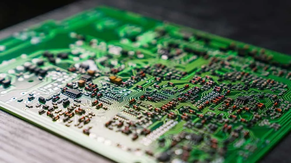
The PCB assembly drawing is crucial for component assembly.
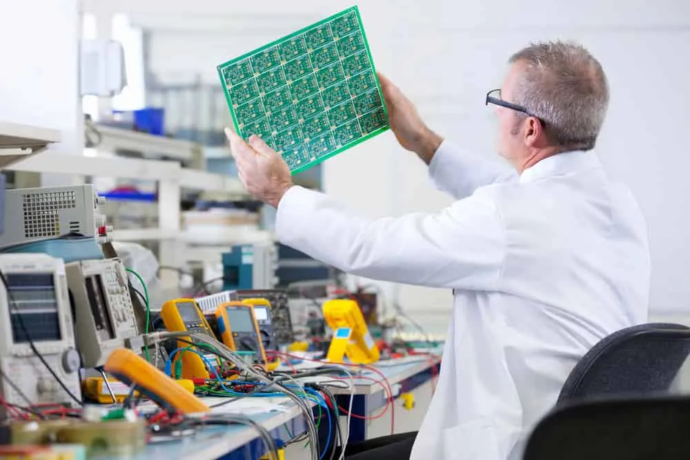
Once your PCB is out of the fabrication line, you need at least four documents before taking it for assembly.
These are board assembly notes, a schematic diagram, a bill of materials (BOM), and a PCB assembly drawing.
Here’s a close-up look at the basics and elements of the PCB assembly drawing document.
What Is a PCB Assembly Drawing?
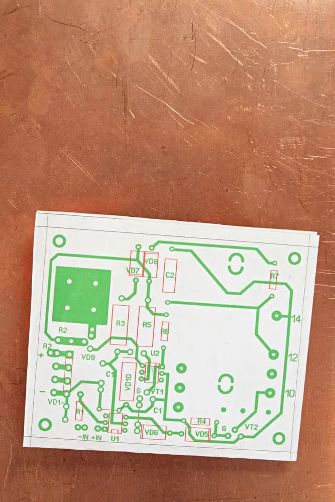
A PCB assembly is a graphical representation of your printed circuit board that shows the component reference designators, their values, tolerance, etc. Additionally, it indicates the following.
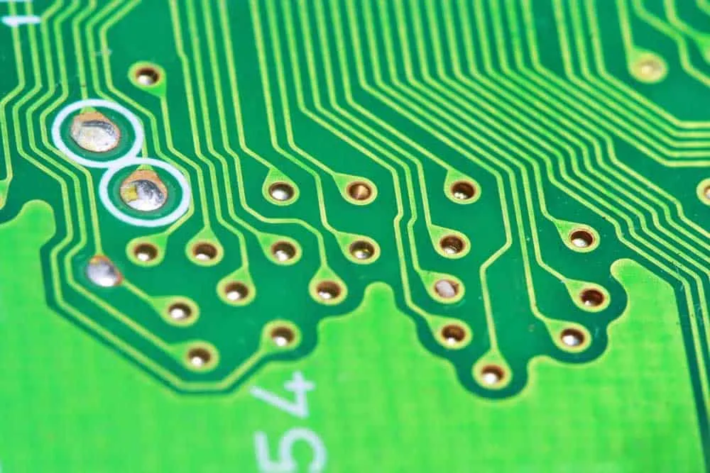
- - Board outline, dimensions, and thickness
- Hole charts
- Layer stack up
- Torque parameters for securing casing screws
- PCB alignment
When dealing with a single-sided board, manufacturers can place the PCB assembly drawing on the back side because there are no electrical conductors.
But with double-sided boards, you need an additional view to show the front and rear sides. If the board is compact, you can include both drawings in a single-page document.
But if large, you’ll need additional sheets to include extended views that show the mechanical element connections in an easier-to-understand way.
Contents of a PCB Assembly Drawing
Always include these items in your PCB assembly drawing.
Drawing Format
Either way, you’ll have to combine this drawing format with the PCB layout created earlier to produce the drawing.
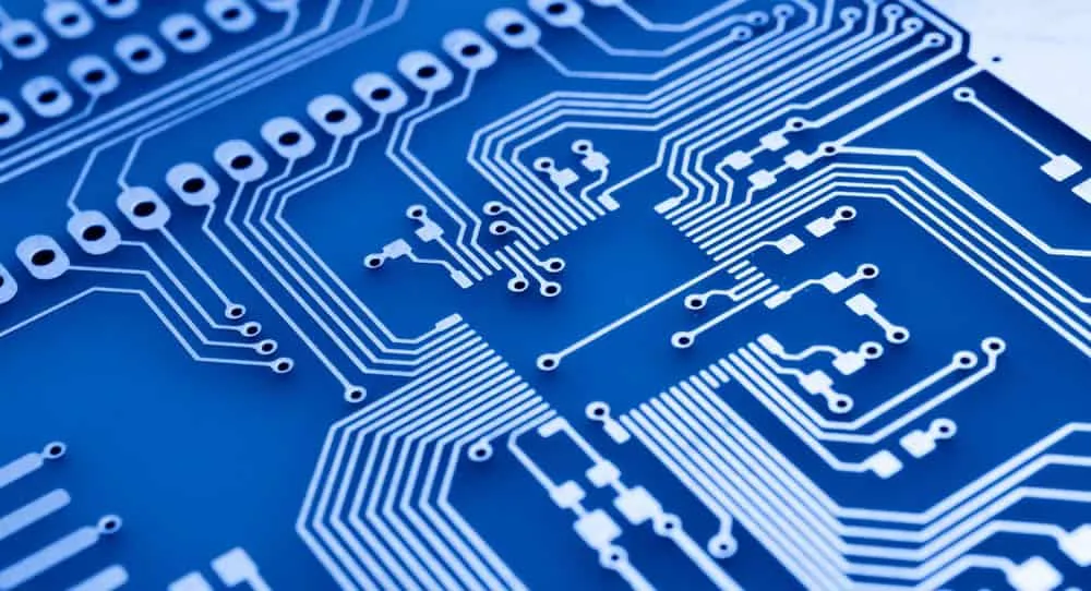
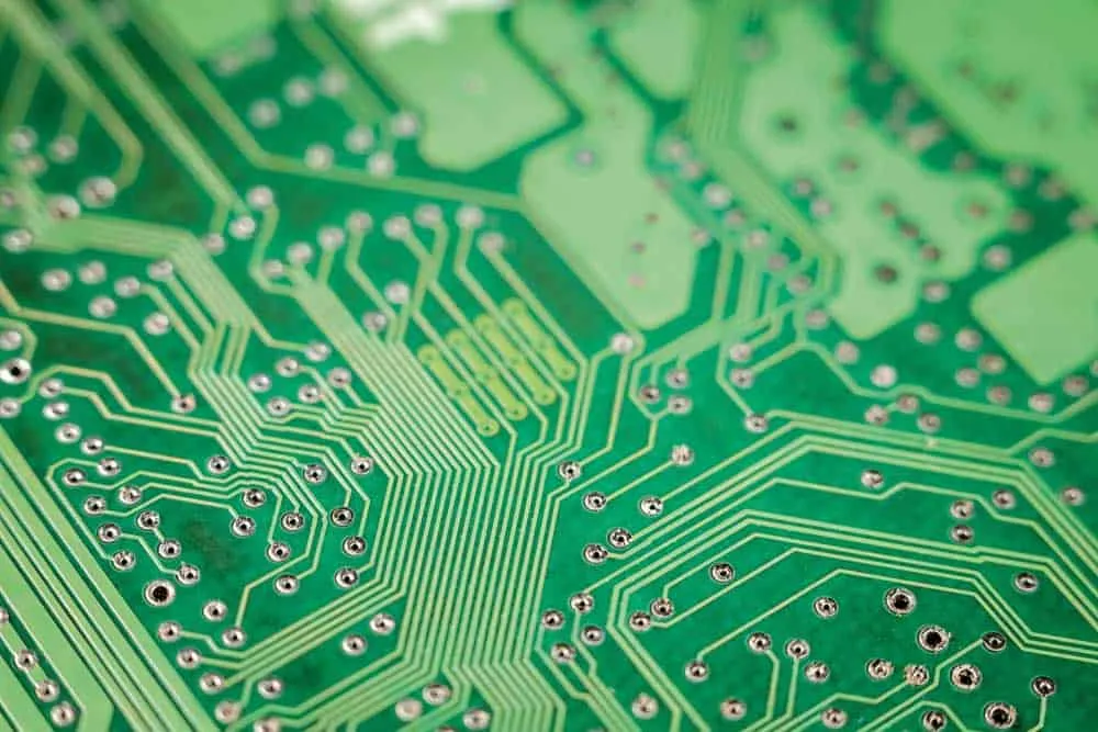
Board Outline
Board outlines include slots & cutouts, and they are high-level PCB design outline representations from the layout database.
The fabrication drawing design document contains the dimensions for the slots and cutouts, but the PCB assembly drawing document only references them.
Identification Information
The drawing should have this information for identifying each unique printed circuit board.
- - Drawing ID number
- Assembly drawing revision label
- Board name
- Contract data
- Corporate address
- Date of creation
Part shapes
Mechanical Parts
Some boards require mechanical parts like shields, connectors, and mounting screws. Since they don’t have the typical circuit board footprint, you might have to add them manually or draw them in a separate sheet.
The CAD footprint library might not represent these components accurately. So adding them separately or manually might be a necessary option.
For instance, the drawing might not indicate an ejector handle because it is neither electronic nor has a typical board footprint.
If the schematic and BOM don’t include this part, use an expanded view of the assembly drawing to list the mechanical part connections.
Assembly Notes
An assembly note is technically a separate document from the assembly drawing, but it must come with the schematic. This document is a production guideline that lists instructions like:
- - Special feature locations
- Industry standards
- Assembly details
- Industry specifications
- Component list (if required by the original manufacturer)
PCB assembly notes have the following functions and benefits.
Designates the Primary Board Side
All circuit boards have two sides: a primary or top side and a secondary or bottom side. This board direction should match the fabrication drawing.
Although it is easy to determine this orientation in the assembly drawing for single-sided boards, it might not be straightforward for double-sided PCBs.
In such a case, the assembly note will highlight the primary side. And you should include an additional view in the PCB assembly drawing to show the layout’s secondary side.
Defines Reference Designators
But generally, PCB assembly drawings are scalable enough to show all the assembly markings. This data should be clear-to-read and be within the component footprint to guide the assembly, field service, and inspection crew.
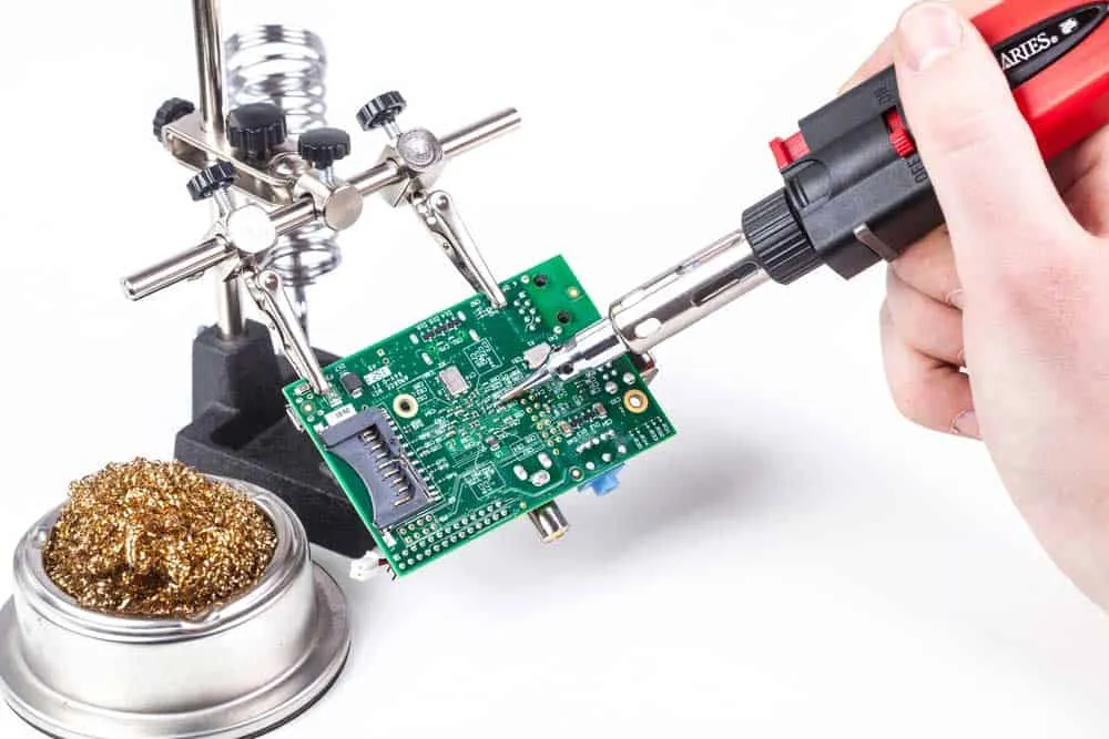
Specifies Soldering Procedures
The assembly note can combine specifications like J-STD-001 and J-STD-003 to specify the quality of the mechanical connections.
J-STD-001 guides how to inspect through-hole solder joints using X-ray machines. This testing process aims to identify the errors or faults you cannot identify with the naked eye or other means.
On the other hand, J-STD-003 highlights the solderability determinations used to verify the PCB manufacturing processes and storage conditions don’t affect solderability.
So the assembly note will have a statement like “solder as per J-STD-001 and J-STD-003 specifications.”
Lists Component Mounting Instructions
Like the soldering procedures, the assembly notes list the mounting instructions using IPC guidelines. For instance, it can state the PCB component mounting must conform to IPC-CM-770. And its acceptability must be to IPC-A-610.
If your board contains manually assembled parts, the drawing/notes should specify the component height restrictions and spacing from other pieces.
Indicates All Specialized Assembly Methods
The notes also specify if the assembly process (soldering) is lead-free. For environmental safety purposes, all PCB soldering processes nowadays utilize lead-free solder.
This specification usually has to do with the IPC-1066 standard. So the document marks the components requiring assembly in-line with this standard.
Manufacturer Label Identification
Lastly, the PCB assembly drawing should have manufacturer identification information like barcodes and assembly tags.
Using a drawing pointer, you can identify the manufacturer label, then reference it in the assembly notes.
Wrap Up
Most people confuse the PCB assembly drawing document with the PCB fab drawing.
But as you can see, the assembly drawing document explains how to fasten every component on the PCB with great detail.
So you can refer to this drawing as the foundation for precise part mounting. And omitting any data can lead to errors and mistakes.
So include the details above to ensure the assembly machine operators program the placement and soldering machine precisely before commencing the process. Explore our PCB assembly services for professional component mounting.
Related Articles
Continue exploring similar topics
Turnkey PCB Assembly
We'll discuss turnkey PCB assembly in this article. Time is money, and you will most likely waste precious time handling some tasks in the PCB assembly process.
How to Surface Mount Solder
Every electronic circuit board you interact with features hole components and surface mount devices. But do you know how to surface mount solder components?
PCB Materials: What Are PCBs Made Of?
Nobody should tell you that the PCB materials don't matter because a circuit board is good as its makeup medium.
Ready to bring your PCB design to life?
Get an instant quote for your custom PCB fabrication and assembly needs.
Get Instant Quote