How To Read PCB Schematics
This is a guide on how to read PCB schematics.A PCB schematic is a circuit diagram designers use in the first stage of the board design process.
This is a guide on how to read PCB schematics.
A PCB schematic is a circuit diagram designers use in the first stage of the board design process.
And the core components of these schematic diagrams are unique circuit symbols that all designers globally can understand.
So knowing these schematics is paramount. And we will look at how to read PCB schematics in this article to get you started. Take a look!
How To Read Circuit Board Schematics?
To read this circuit board diagram, you need to know these four things.
Reference Designator
The REFDES states the name or reference for each component, showing its location on the PCB. It usually consists of one or two letters followed by a number.
Component Symbol
Component symbols are the most conspicuous parts of PCB schematic diagrams. The industry-standard shapes indicate the structures that form the circuit.
Network
The network is the wiring or electrical connections between components.
Output
Outputs primarily include netlists and a Bill of Materials, which match the REFDES.
Schematic Symbols for Electronic Components
The most typical symbols include:
Resistors
Almost all circuit boards have resistors because they are critical passive components for restricting electrical current flow.
The component’s symbol can either be a zigzag line (US) or a rectangle with leads on two sides (international standard).
There are also variable resistors that increase or decrease the resistance to electrical current flow depending on external input.
They include analog resistance sensors like thermistors, potentiometers, and photoresistors.
Photoresistor
Also known as an LDR (Light Dependent Resistor), a photoresistor relies on varying light levels to provide the external input. So it is an optoelectronic device and has a different circuit symbol.
Potentiometer
Potentiometers are 3-terminal variable resistors that use rotating/sliding contacts to adjust a voltage divider, which alters the resistance.
So instead of sensing signals like light automatically, a potentiometer needs manual input.
Its circuit symbol has an arrow to indicate the wiper where the output voltage or signal gets derived.
Capacitors
Capacitors are also passive components, but their purpose is to store electrical charge. They come in two types.
Polarized
Non-Polarized
Non-polarized capacitors have lower capacitance values than their polarized counterparts.
But the most significant difference is that this type has no positive or negative ends. So you can connect it in any orientation in the circuit.
Inductor
Inductors are coils wound around core materials to generate a magnetic field when electrical current flows through them. And they come in two types.
But magnetic-core inductors have magnetic cores (iron) to enhance their inductance performance.
Their symbol resembles the air-core inductor but has two parallel lines next to the squiggly line.
Diode
Diodes are active electronic components that permit electrical current to flow in only one direction.
So they have positive leads (anodes) and negative terminals (cathodes). The former is the end with a flat triangle edge on the symbol.
But the component comes in several types.
LED
Light Emitting Diodes are optoelectronic devices that emit light when electrical current flows through them in one direction.
Zener
Zener diodes allow current to flow either in a forward or reverse bias. The condition for switching current flow is when the voltage across the terminals exceeds a specified threshold.
Schottky
This component is a low-voltage diode that switches faster than the regular diode.
Power Sources
An electrical circuit needs an electrical current to flow through the components, which must come from a power source. It can be either of the following.
DC
DC voltage power sources supply electrical energy that flows in one direction. The circuit symbol for DC power is usually a circle that encloses positive and negative voltage signs (+ and -).
AC
Single-Cell Battery
Batteries supply direct current. So the power source has polarized terminals.
The component’s circuit symbol consists of two parallel lines. And the longer one is the positive terminal.
Multi-Cell Batteries
Multi-cell batteries combine several single-cell units connected in series. So the circuit symbol usually consists of four parallel lines that alternate between long and short.
Transistors
Transistors are vital active circuit components that enable the creation of digital logic gates in modern electronic devices.
Their purpose is to either switch or amplify electrical signals.
And they do these functions using semiconductor materials with three terminals minimum.
Most are BJTs (Bipolar Junction Transistors) with these three terminals: base, collector, and emitter. The typical BJT types include:
- - NPN Transistor: A negative-positive-negative transistor with an arrow pointing from the middle to the emitter terminal.
- PNP Transistor: A positive-negative-positive transistor with an arrow pointing from the emitter to the middle connection.
MOSFETs are also typical 3-terminal transistors. But their terminals are different (gate, drain, and source). Also, the connections inside the circle have different shapes.
Instead of the “triangular-like” BJTs, MOSFETs have a horizontal T connecting to the gate terminal. And the drain-source connection is via lines joined at 90° angles.
Terminals
Terminals are external circuit connection points with empty circles as their circuit symbols. In contrast, junctions or nodes have solid rings.
Switches
Switches link or break circuit connections, but some can change the electrical current flow path. They include:
SPST
Single-Pole, Single-Throw switches are simple on/off, 2-terminal switches.
SPDT
SPDT stands for Single-Pole, Double-Throw. So it has one input and two output terminals, and the input can only connect to one output terminal at a time.
This connection enables you to change states or current flow in a circuit.
DPST
Double-Pole, Single-Throw switches are equivalent to two SPST switches controlled by a shared mechanism. So the symbol resembles two SPST switches.
DPDT
Double-Pole, Double-Throw switches are equivalent to two SPDT switches controlled by a shared mechanism. Therefore, the circuit symbol resembles two SPDT switches.
Momentary
Momentary switches change between closed and open states after being pressed, and the most typical type is the push button.
Integrated Circuit
Circuit boards are compact circuits, but integrated circuits take the compactness to a new level.
Depending on the IC, it can pack hundreds, thousands, or millions of components (transistors, capacitors, and resistors) in tiny packages.
So you can have several integrated circuits in a PCB, including:
- - Audio amplifiers
- Oscillators/timers
- Operational amplifiers
- Flip-flops
- Dual operational amplifier
Transformer
Air-Core Transformer
The symbol for these transformers consists of two squiggly lines opposite each other. They are ideal for transferring RF currents between circuits but have massive flux losses.
Iron Core Transformer
Iron-core transformers enhance the air-core transformer design by reducing flux losses into the air. So more electrical energy gets transferred to the secondary coil.
The component has two parallel lines between the squiggly lines.
Multi-Winding Transformer
Instead of having one continuous wire winding, these transformers can have two or more. The circuit symbol will have gaps between the squiggly lines to show they are separate.
Center-Tapped Transformer
These transformers have two connected secondary windings. So they share the connections, but each one outputs a different voltage.
The circuit symbol resembles an iron-core transformer but has a center tap-line on the secondary winding.
Current Transformer
Electrical current transformers output alternating current from the secondary coil proportional to the primary winding current.
The component’s function is to lower high-voltage currents for protection/monitoring purposes.
Relay
Relays are electromagnets used to operate switches electrically. The electromagnet connects to an actuator that closes or opens the relay depending on the current applied to the coil.
Speaker
Speakers convert electrical pulses or signals into sound energy using a magnetic core and moving coil attached to a cone.
The component’s schematic symbol resembles a physical speaker.
Fuse
Current spikes can damage a circuit’s physical components, so it is necessary to have a safety mechanism.
Fuses provide overcurrent protection using a thin wire that heats, melts, and creates a discontinuity if there is excessive current.
Microphone
Microphones are transducers that convert sound waves into electrical pulses.
Motor
But some, such as stepper and three-phase motors, have multiple terminals. So you must be careful when wiring these devices to switch the rotational direction.
Antenna
Antennas are electronic devices that transmit or receive radio signals.
Non-Component Schematic Symbols
Some schematic symbols don’t represent any electronic components. Instead, they indicate the presence of physical structures built into the PCB. They include the following.
Grounds
Grounds are current return paths in circuits and are negative signal connections. They come in the following types.
Earth Ground
Common Signal Ground
Chassis Ground
Test Points
As the name suggests, test points are exposed copper pads on the board used to test PCB functions.
Logic Gates
Logic gates are functions, not PCB components. Transistors usually provide these functions by manipulating voltages to produce logic highs and lows (ones and zeros).
They include the following.
- AND
- - NAND
- OR
- NOR
- NOT
- XOR
- XNOR
Wires and Connections

The components, non-components, and logic gates need electrical connections between them. These links require wires or PCB traces, which have the following representations in circuits at intersections.
- - Physical connection (node or dot)
- No link (no node/dot)
Alternatively, you can place a tiny semi-circle above the intersection to show the wires have no electrical connection.
Wrap Up
In conclusion, PCB schematics are critical starting points for modeling circuits, so designers need to understand what the symbols mean.
And we hope this article will get you up to speed with the meaning of these schematic symbols. But in case we left something out, contact us. We’ll be happy to receive and act on your feedback. Ready to turn your schematic into reality? Check out our PCB manufacturing and prototype services.
Related Articles
Continue exploring similar topics
How to Identify Diodes
Learn how to identify diodes by type and polarity. Understand markings, use multimeter testing, and recognize common diode types for your electronic projects.
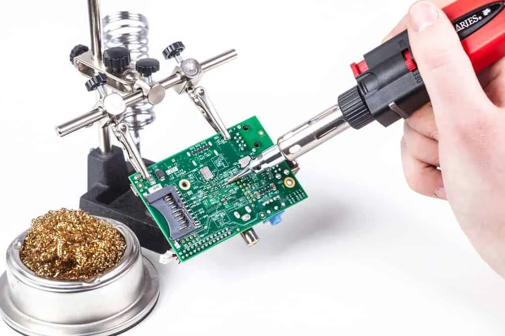
How to Solder Wires to a Circuit Board
Do you know how to solder wires to a circuit board? It is straightforward, but you must perform it correctly to ensure a perfect electrical connection.

How To Mix Ferric Chloride for Etching
Learn how to mix ferric chloride for PCB etching. Get the right ratios, safety tips, and step-by-step instructions for etching copper-clad boards at home.
Ready to bring your PCB design to life?
Get an instant quote for your custom PCB fabrication and assembly needs.
Get Instant Quote